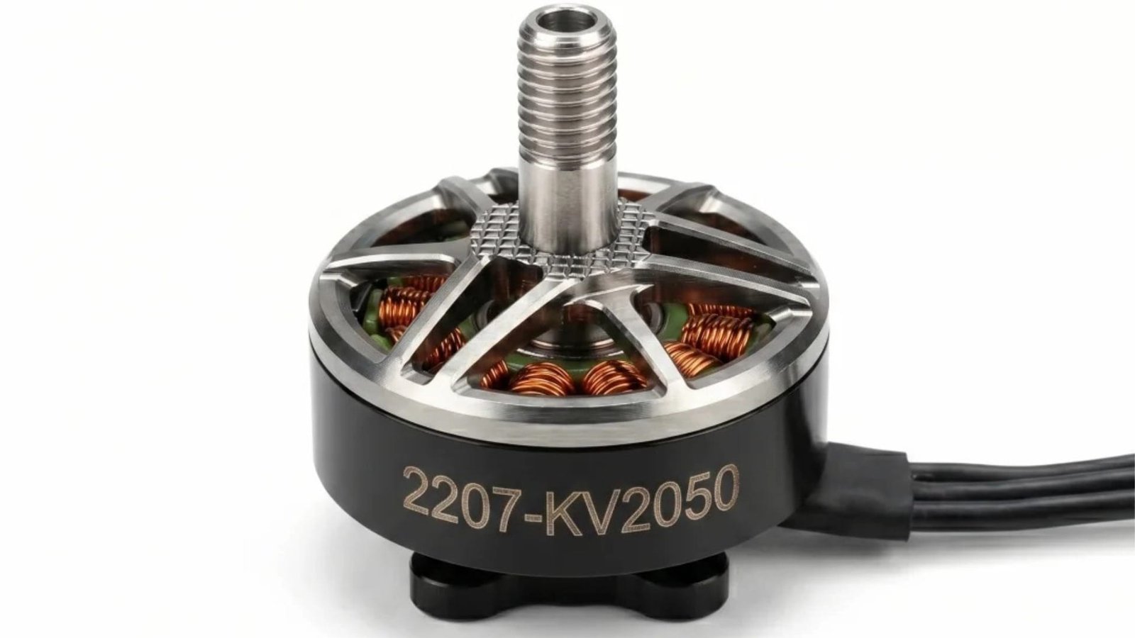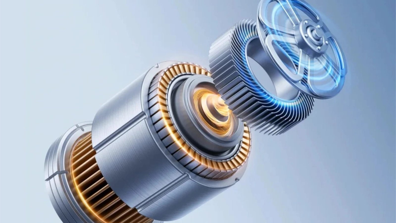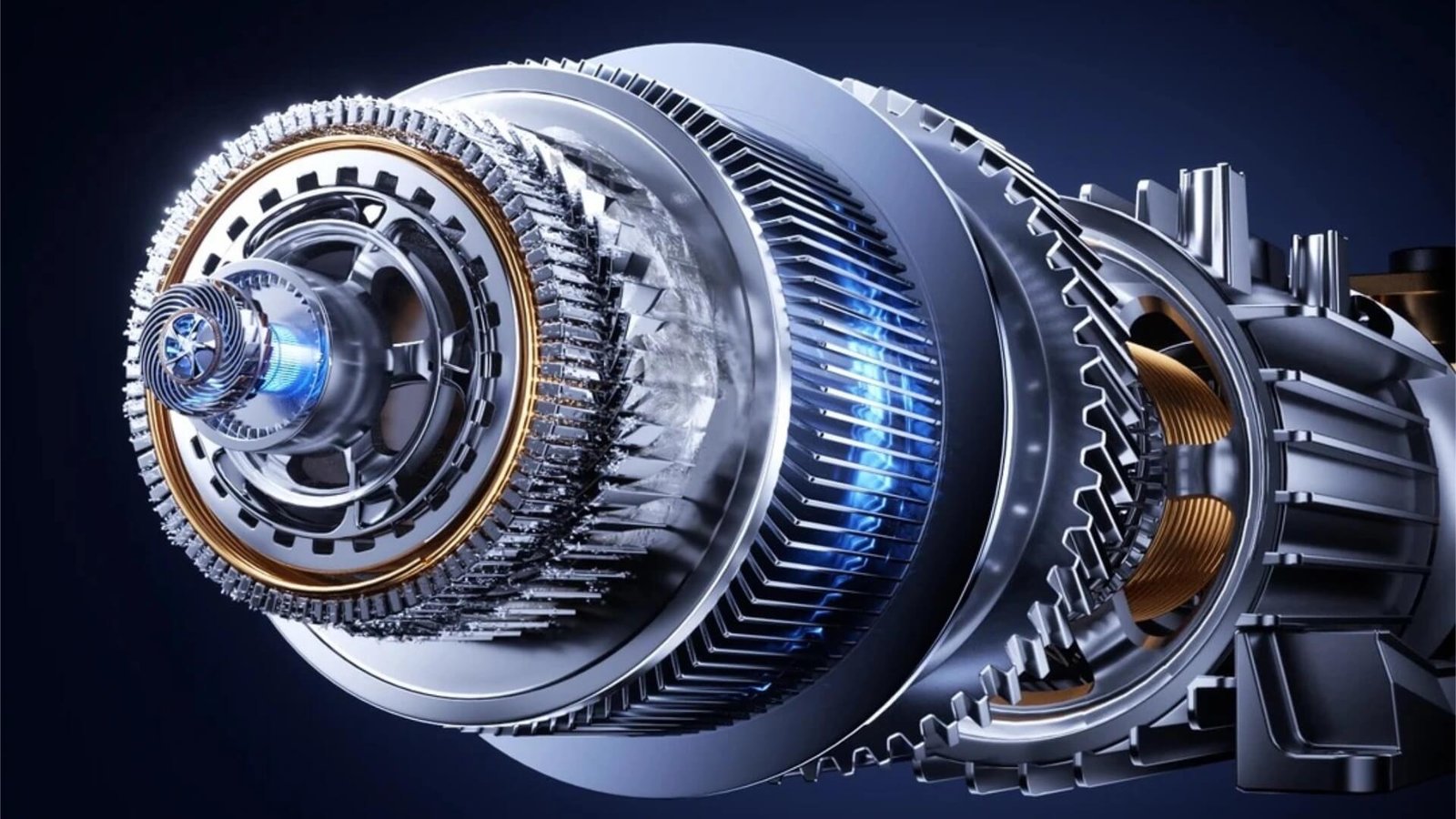
Brushless DC (BLDC) motors have become ubiquitous across modern industry — powering everything from cordless power tools and drone propulsion systems to home appliances, automotive auxiliary systems, and precision industrial automation. Their rise is driven by a combination of high efficiency, compact size, long service life, and excellent controllability. But behind every high-performance BLDC motor lies a precision-engineered motor core, and behind every motor core lies a stamping die that must meet extraordinary demands.
The lamination stacks used in BLDC motors differ significantly from those in traditional induction motors. They are typically smaller, thinner, and require much tighter geometric tolerances. The slot geometries are more complex, the air gap is smaller, and the production volumes are often enormous. These factors create a unique set of challenges for motor core die design — challenges that require specialized materials, advanced manufacturing precision, and deep domain knowledge.
This article explores the key design considerations, technical challenges, and proven solutions for BLDC motor core stamping dies. Whether you are developing a new BLDC motor platform or seeking to optimize an existing production line, this guide will help you understand what it takes to build tooling that delivers precision, speed, and longevity in the demanding world of compact high-efficiency motors. Our BLDC Motor solutions page provides complementary information on how our tooling is tailored specifically to this motor category.
1. The Rise of BLDC Motors and Their Tooling Demands
The global BLDC motor market has experienced explosive growth over the past decade, driven by several powerful trends:
- Cordless electrification: Power tools, garden equipment, and household appliances are rapidly transitioning from AC universal motors to battery-powered BLDC designs that offer higher efficiency and longer runtime.
- Drone and e-mobility expansion: The drone market, e-bikes, and electric scooters all depend on lightweight, high-speed BLDC motors for propulsion.
- Automotive electrification: Beyond main traction motors, modern vehicles contain dozens of auxiliary BLDC motors — powering HVAC blowers, electric power steering, oil pumps, cooling fans, and seat actuators.
- Industrial automation: Servo systems, robotics, and precision actuators increasingly use BLDC motors for their responsiveness and reliability.
Each of these applications places specific demands on the motor core — and by extension, on the stamping die that produces it. A BLDC stator for a power tool may have an outer diameter of only 40mm but require slot tolerances measured in microns. A drone motor stator may use 0.20mm silicon steel to minimize core losses at very high operating frequencies. Production volumes for popular consumer applications can reach millions of units per year, demanding tooling that maintains precision over hundreds of millions of strokes.
The tooling implications are clear: BLDC motor core dies must be designed for precision, speed, and longevity from the very first concept. This starts with our die design and engineering team, who analyze every BLDC lamination design for manufacturability, material compatibility, and long-term performance before the die is built.
2. Key Characteristics of BLDC Motor Cores
To design an effective BLDC motor core die, you must first understand what makes these laminations unique.
Stator and rotor geometry
BLDC motor stators typically feature:
- Multiple slots: Common configurations include 6, 9, 12, 18, or 24 slots, depending on the pole count and winding scheme. Slot openings are often narrow and deep, requiring slender punches with high precision.
- Small air gap: BLDC motors are designed with tight air gaps to maximize torque and efficiency. This requires exceptional concentricity between the stator inner diameter and the rotor outer diameter.
- Thin teeth: To maximize slot area for windings while minimizing magnetic saturation, BLDC stator teeth are often narrow and tall. The punches that form these teeth must be robust despite their slender geometry.
- Compact size: Many BLDC stators are under 60mm in outer diameter, making the die components small and precise. This miniaturization increases the difficulty of maintaining clearance and alignment.
Common silicon steel grades and thicknesses
BLDC motors operate at higher frequencies than induction motors, which drives the use of thinner, higher-grade silicon steel to minimize eddy current losses:
| Application | Typical Thickness | Common Grades |
|---|---|---|
| Power tools | 0.35mm | 35A300, 35W300, M270-35A |
| Home appliances | 0.35–0.50mm | 35A300, 50A470 |
| Drones & UAVs | 0.20–0.27mm | 20A1500, 27A230 |
| Automotive auxiliary | 0.27–0.35mm | 27A230, 35A300 |
| Industrial servo | 0.20–0.27mm | 20A1500, 27A230 |
The thinner the silicon steel, the tighter the die clearances must be — and the more critical the tool material selection becomes. As we detailed in our article on silicon steel grade and insulation coating impact, high-silicon thin-gauge materials demand carbide cutting edges and precision guidance to maintain burr control and dimensional stability over long production runs.
Stacking methods
Most BLDC motor cores use auto-interlocking (self-riveting) for stator stacking. The interlocking dimples are formed directly in the progressive die, allowing the stack to exit the die as a bonded unit ready for winding. Some premium applications specify gluing (self-adhesive bonding) to maximize magnetic performance, which requires the die to produce flat, adhesive-ready lamination surfaces without interlock dimples. We covered both technologies in depth in our article on EV motor core die design — and while BLDC motors are smaller than EV traction motors, many of the same stacking technology considerations apply.
3. BLDC Motor Core Die Design Challenges
The compact size and tight tolerances of BLDC motor cores create several design challenges that are more acute than in larger motor types.
Thin-gauge stamping burr and edge quality control
With silicon steel thicknesses down to 0.20mm, BLDC laminations are at the extreme end of thin-gauge stamping. At this thickness, even a burr of 0.010mm represents 5% of the material thickness — enough to degrade stacking factor, increase interlaminar eddy currents, and compromise motor performance.
The challenges are compounded by the small feature sizes. A BLDC stator slot opening might be only 2mm wide, with tight tolerance bands. Burr formation along the slot edges must be kept below 0.010mm consistently, not just at die tryout but throughout the die’s life. This requires:
- Optimal cutting clearances (typically 3–5% of material thickness per side)
- Razor-sharp cutting edges maintained through proper material selection and regrind discipline
- Guided strippers that prevent punch deflection even at high speeds
- Regular burr measurement as part of the maintenance routine
Our comprehensive guide on reducing burr height in motor lamination stamping applies directly to BLDC applications, and we strongly recommend reviewing it alongside this article.
Air gap concentricity and roundness
The air gap in a BLDC motor is the radial space between the stator inner diameter and the rotor outer diameter. It is the primary magnetic interface in the motor — and the smaller it is, the more efficient the motor can be. In compact BLDC motors, air gaps of 0.25–0.50mm are common, meaning the concentricity and roundness of both stator and rotor laminations must be controlled to within microns.
For a compound die, which cuts both stator ID and rotor OD in a single stroke, concentricity is inherent. For a progressive die, however, maintaining perfect stator-to-rotor concentricity requires exceptional alignment control throughout the die. The stator and rotor are typically stamped side by side in the same strip, and any accumulated feed error, pilot misalignment, or station-to-station variation will degrade concentricity.
The solution is a combination of precision manufacturing, rigid guidance, and careful station layout. Our precision manufacturing team uses slow-wire EDM and jig grinding to ensure that every die component is machined to sub-micron tolerance, and that all stations are aligned to a common reference frame. This is not a matter of luck — it is a matter of measuring and controlling every dimension.
Slender punch strength and guidance
The narrow teeth and small slot openings of BLDC stators require punches with very small cross-sections — often 1–3mm wide and 20–40mm long. These slender punches are prone to buckling under the cutting load, especially at high speeds where dynamic forces are amplified.
Several design measures mitigate this risk:
- Stepped punch design: The punch body is made larger than the cutting tip, with a smooth radius transition. This increases the punch’s effective stiffness without changing the cut profile.
- Fully guided strippers: The stripper plate provides continuous lateral support to the punch tip, preventing deflection during the cutting stroke. This is particularly critical for slender punches at high speed.
- Carbide punch material: Tungsten carbide’s high elastic modulus (550–650 GPa) means it deflects less under load than steel — a crucial advantage for slender BLDC punches.
At ZHIXIANG, our motor core progressive die designs for BLDC applications incorporate all three strategies as standard. The result is punches that cut cleanly and last longer, even in the most demanding slot geometries.
High-speed stamping and thermal management
BLDC motor production volumes are often extremely high — millions of units per year for popular power tool and appliance platforms. This drives the need for high-speed stamping, typically 400–600 SPM or higher. At these speeds, the challenges of heat generation, vibration, and dynamic stability become prominent.
The thermal and dynamic considerations for BLDC dies are similar to those we covered extensively in our article on high-speed stamping die design optimization. Key strategies include:
- Carbide cutting edges for hot hardness and thermal conductivity
- DLC or TiAlN coatings to reduce friction and provide thermal protection
- Ball-bearing guidance to eliminate play at high cycling frequencies
- MQL lubrication to deliver minimal, consistent oil mist
- Thermal compensation in clearance calculations
The small size of BLDC dies offers one advantage: their compact mass heats up faster but also cools faster, making thermal equilibrium easier to reach. However, the precision requirements are tighter, so thermal management remains critical.
Auto-interlocking reliability
Most BLDC stators use auto-interlocking for stack assembly. The interlocking dimples are small — typically 0.5–1.5mm in diameter — and must be formed with precise depth and geometry to ensure reliable stacking without damaging the insulation coating or distorting the lamination.
In a progressive die, the interlocking station is typically one of the final operations. It requires:
- Precise punch and die geometry to form clean dimples without tearing
- Controlled punch depth to achieve consistent interlocking force
- Robust punch construction to withstand the forming force without breakage
- Integration with stack counting to control stack height
The reliability of the auto-interlocking system directly affects downstream productivity. A die that produces inconsistent stacks causes jams in the stacking chute, misaligned stacks, and assembly problems. Our die designs incorporate proven interlocking geometries and have been validated across thousands of motor core programs.
4. Tool Material and Coating Selection for BLDC Dies
Material selection is one of the most consequential decisions in BLDC motor core die design. The combination of thin-gauge silicon steel, tight tolerances, and high production volumes demands premium materials.
Tungsten carbide for cutting components
For high-volume BLDC motor production, sub-micron grain tungsten carbide is the material of choice for all cutting punches and die inserts. The reasons are clear:
- Wear resistance: Silicon steel’s insulation coating — especially the inorganic C5 and C6 types — is abrasive. Carbide maintains a sharp cutting edge far longer than any tool steel.
- Stiffness: Carbide’s high elastic modulus is critical for the slender punches used in BLDC slot forming. It minimizes deflection under load.
- Thermal stability: Carbide retains its hardness at elevated temperatures, essential for high-speed operation.
- Dimensional stability: Carbide’s low thermal expansion keeps clearances tight and consistent through thermal cycling.
Our tungsten carbide stamping die page provides a comprehensive overview of how we apply carbide technology to motor core applications — including BLDC dies with 0.20mm thin-gauge capability.
PM tool steel for structural components
While carbide is preferred for cutting edges, powder metallurgy tool steels like ASP23 and VANADIS 4 remain excellent choices for structural components — die plates, strippers, retainers, and guides. They offer good wear resistance, excellent toughness, and are more forgiving in impact situations than carbide.
Coating strategies for BLDC applications
The insulation coating on the silicon steel — whether organic (C3) or inorganic (C5/C6) — dictates the optimal die coating:
- DLC (Diamond-Like Carbon): Best for organic and semi-organic coatings. Its ultra-low friction coefficient prevents adhesive pickup, keeping punches clean and reducing edge wear.
- TiAlN (Titanium Aluminum Nitride): Ideal for inorganic coatings and high-speed operation. Its thermal stability and hardness provide excellent abrasive wear resistance.
- CrN (Chromium Nitride): A versatile option for semi-organic coatings, balancing low friction with good hardness.
The coating choice must also consider the punch substrate. Carbide punches with DLC coatings represent the ultimate combination for thin-gauge BLDC stator stamping: the stiffest, most wear-resistant substrate combined with the lowest-friction surface available. This is our default recommendation for high-volume BLDC programs.
5. Progressive Die Design for BLDC Stator and Rotor
Most BLDC motor cores are produced in a motor core progressive die, with the stator and rotor stamped side by side in the same strip. The progressive architecture offers the speed, precision, and integration capability needed for high-volume BLDC production.
Strip layout and station arrangement
A typical BLDC progressive die follows this sequence:
- Piloting and pre-piercing: Pilot holes are pierced for precise strip positioning in later stations; rotor shaft holes and ventilation features are also pre-pierced.
- Rotor slot notching: The rotor slots are cut progressively — typically over 2–4 stations — to reduce the load on individual punches and improve edge quality.
- Stator slot cutting: Stator slots are similarly cut over multiple stations. The stator teeth are formed progressively, with each station cutting a portion of the final slot shape.
- Rotor and stator separation: The rotor is blanked from the strip, often with integrated auto-stacking if required.
- Stator blanking and stacking: The finished stator is blanked, with interlocking dimples formed and stack height controlled via a counting mechanism.
- Final stack ejection: The completed stator and rotor stacks exit the die, ready for winding and assembly.
The exact station count depends on the lamination geometry and feature density. A simple 6-slot BLDC stator for a small appliance motor might need 8–10 stations, while a complex 24-slot stator for an industrial servo motor might require 14–18 stations.
Punch guidance and stripper design
As emphasized throughout this article, the slender punches used in BLDC slot cutting demand exceptional guidance. Our die designs incorporate:
- Ball-bearing guide posts for zero-play alignment of the entire punch assembly
- Fully guided strippers with hardened, replaceable guide inserts around every punch
- Multi-level stripper designs for complex station layouts, providing support at the appropriate height for each operation
- Punch retainers with anti-rotation features to maintain orientation of non-circular punches
These features work together to ensure that every punch enters its die opening at the correct angle and position, every stroke, at any speed.
Auto-stacking station design
The auto-interlocking station is one of the most critical components in a BLDC stator die. It must form the interlocking dimples with precise depth and geometry, then stack the laminations with the correct rotational alignment and stack height.
Key design elements include:
- Interlocking punch geometry: The dimple shape — typically round, rectangular, or V-shaped — must be optimized for the material thickness and stacking force required. The punch must be robust enough to withstand the forming force without breakage.
- Stack counting mechanism: A mechanical or electronic counter tracks the number of laminations in each stack and triggers ejection when the target height is reached.
- Stack alignment features: Rotational alignment is maintained through the geometry of the interlocking dimples themselves, which must be arranged symmetrically to ensure consistent orientation.
- Controlled ejection force: The finished stack must be ejected with enough force to clear the die but not so much that it damages the laminations.
We have refined these designs over thousands of BLDC motor core die projects, and our engineering team can advise on the optimal stacking strategy for any BLDC lamination design. The die design and engineering page provides additional detail on how we approach these complex systems.
6. Achieving Tight Tolerances: Air Gap and Concentricity
The air gap is the lifeblood of a BLDC motor’s performance — and controlling it starts with the lamination die. Achieving tight air gap tolerances in a progressive die requires a holistic approach:
Precision manufacturing as the foundation
Every component in the die — punches, die inserts, guide elements — must be manufactured to sub-micron tolerances. At ZHIXIANG, our precision manufacturing team uses:
- Slow-wire EDM for profile cutting with ±0.001mm accuracy
- Jig grinding for final sizing of critical dimensions
- CMM inspection to verify every component against the design intent
- Laser alignment to ensure all stations are positioned correctly relative to each other
Without this manufacturing precision, even the best design cannot deliver the concentricity and roundness required for small air gaps.
Assembly and alignment discipline
Die assembly is as important as component manufacturing. All plates must be assembled with precision alignment pins, and the assembled die must be checked for parallelism, alignment, and clearance at every station. Our assembly process includes:
- Bench assembly under controlled conditions to prevent contamination and misalignment
- Post-assembly CMM verification of punch-to-die clearance at every station
- Dynamic testing at increasing speeds to verify stability before delivery
Clearance optimization for concentricity
The progressive die design must ensure that the stator inner diameter and rotor outer diameter are stamped with consistent clearance, minimizing the variation that would degrade concentricity. This involves:
- Common datum reference for all stations
- Pilot pin positioning that maintains strip location relative to the die
- Minimum station-to-station transfer to reduce accumulated error
When these elements are executed properly, BLDC motor core dies can achieve stator-to-rotor concentricity that rivals compound dies — while delivering the speed and integration benefits of progressive architecture. Our article on reducing burr height in motor lamination stamping discusses the importance of clearance uniformity for edge quality, which applies equally to concentricity control.
7. High-Speed Stamping and Thermal Management for BLDC Production
BLDC motor production often operates at the highest stamping speeds in the motor industry — 400–600 SPM is standard, and some applications push toward 800 SPM. At these speeds, the principles we covered in our article on high-speed stamping die design optimization become essential reading.
Speed optimization for BLDC dies
While BLDC dies share many high-speed characteristics with other motor core dies, a few factors are specific to this segment:
- Small die size: The compact dimensions of BLDC dies mean shorter punch strokes and less reciprocating mass. This is advantageous for high-speed operation, as the dynamic forces are lower than in larger dies.
- Thinner materials: BLDC laminations are among the thinnest stamped in the motor industry, requiring proportionally tighter clearances. This makes thermal management more critical, as even small dimensional changes can affect clearance significantly.
- Higher cycling frequencies: At 600 SPM, the die experiences 10 cycles per second. The natural frequencies of the die structure must be kept well above this rate to avoid resonance. The small, stiff structure of BLDC dies is helpful here.
Thermal management strategies
Effective thermal management in BLDC dies combines:
- Carbide cutting edges with high thermal conductivity to carry heat away from the interface
- DLC coatings to minimize frictional heat generation
- MQL lubrication to provide evaporative cooling at the cutting interface
- Directed air blasts for continuous convective cooling
- Thermal compensation in clearance calculations to account for operating temperature expansion
The goal is a die that reaches thermal equilibrium quickly and maintains stable clearances throughout the production run. This is particularly important for BLDC dies running 24/7 in high-volume production environments, where thermal drift can cause quality issues if not properly managed. Our high-speed stamping die design article covers these strategies in depth.
8. Case Example: BLDC Motor Core Die for Power Tool Applications
To illustrate how these principles translate into practice, consider a recent BLDC motor core die project for a cordless power tool application:
Motor specifications:
- Stator OD: 48mm
- Rotor OD: 26mm
- Stator slots: 12
- Rotor poles: 8
- Silicon steel: 0.35mm M270-35A (2.2% Si)
- Insulation coating: C5 semi-organic
- Stacking: Auto-interlocking, 6 dimples per stator lamination
- Target speed: 450 SPM
- Burr requirement: ≤0.012mm
- Air gap concentricity: ≤0.030mm
Die specifications:
| Parameter | Specification | Rationale |
|---|---|---|
| Die type | Progressive die, 12 stations | Speed and integration for high volume |
| Cutting components | Sub-micron tungsten carbide (WC-8Co) | Wear resistance on C5 coating |
| Punch coating | DLC on all cutting punches | Low friction, anti-adhesion |
| Guidance | Ball-bearing guides + fully guided stripper | Zero-play at 450 SPM |
| Clearance (cold) | 0.018mm per side (5.1% t, thermally compensated) | Optimal running clearance at temperature |
| Lubrication | MQL vanishing oil, 6 ml/hour | Minimal residue on lamination stack |
| Auto-stacking | 6-dimple interlocking with stack counter | Reliable stack height control |
Performance results:
| Metric | Result |
|---|---|
| First tryout burr height | 0.005–0.008mm |
| Burr height at 50M strokes | 0.007–0.010mm |
| Air gap concentricity | 0.022mm (target ≤0.030mm) |
| Stack height variation | ±0.05mm |
| First regrind | At 85 million strokes |
| Total projected die life | >250 million strokes |
This project — typical of our work with Power Tools Motor customers — demonstrates that with proper design, material selection, and manufacturing precision, BLDC motor core dies can deliver exceptional performance at high speeds with minimal maintenance intervention.
Similar results have been achieved across the full range of BLDC applications: Home Appliance Motor platforms, Drone & UAV Motor programs using 0.20mm silicon steel, and high-precision industrial servo applications. The underlying engineering principles remain constant; only the specific parameters change with each application.
9. Conclusion: Partnering for BLDC Motor Core Tooling Success
The BLDC motor revolution shows no signs of slowing. As motors become smaller, more efficient, and more integrated into every aspect of modern life, the demands on motor core tooling will only intensify. Manufacturers who succeed in this market will be those who partner with die suppliers that understand the unique challenges of BLDC motor core stamping — and have the engineering depth, manufacturing precision, and practical experience to solve them.
At ZHIXIANG (motordie.com), we have built our reputation on delivering high-performance motor core dies for the most demanding BLDC applications. From thin-gauge drone motor stators to high-volume power tool cores, our motor core progressive dies combine precision, speed, and longevity to deliver exceptional total value. Every die is engineered from the ground up for its specific application, with material selection, coating strategy, guidance design, and thermal management all tailored to the requirements at hand.
Ready to optimize your BLDC motor core tooling? Send us your lamination drawing, silicon steel specification, and production targets. Our engineering team will provide a detailed technical proposal — including material selection, coating recommendations, and a complete die design strategy — within 48 hours. Send your drawing today and let’s build the tooling foundation for your next BLDC motor platform.