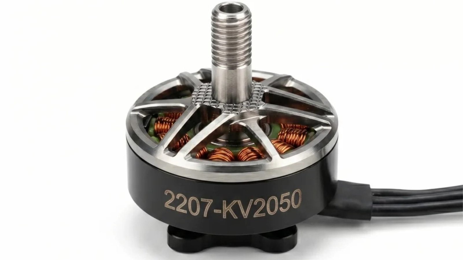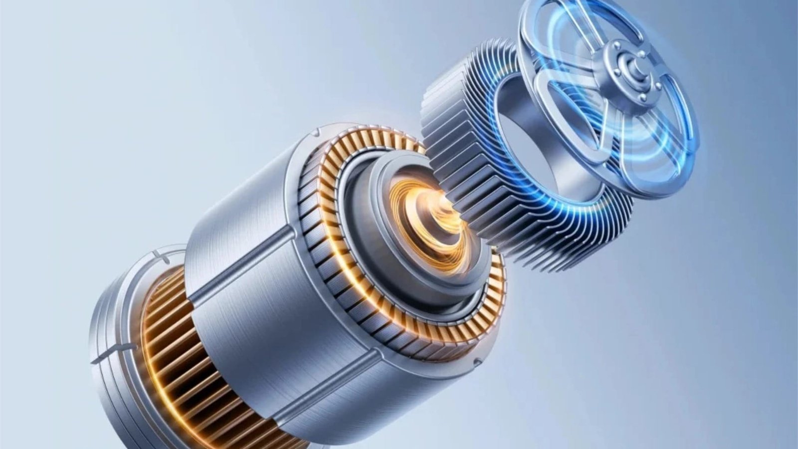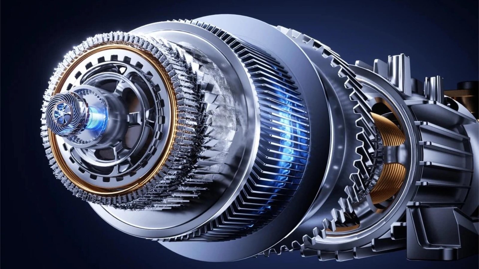
Choosing the right motor core stamping die is one of the most critical decisions in electric motor manufacturing. Whether you produce stator and rotor laminations for EV traction motors, home appliances, power tools, or industrial servo motors, the tooling you select directly affects part precision, production speed, die life, and overall cost per stroke.
Three main types of dies dominate the motor lamination industry: progressive dies, compound dies, and tungsten carbide (carbide) dies. Each has its own strengths, ideal application range, and technical boundaries. This comprehensive guide will help engineers, purchasing managers, and motor manufacturers make an informed decision by exploring every critical factor — from material thickness and production volume to precision requirements and tooling cost.
1. Understanding the Core Die Types
Progressive Die (Motor Core Progressive Die)
A progressive die — also called a progressive stamping die or multi-station die — performs a series of cutting, notching, and forming operations at different stations. The strip of electrical steel (silicon steel) advances through the die with each press stroke. By the final station, the finished stator and rotor laminations are separated, often with automatic stacking (interlocking) features integrated directly into the tool.
Key characteristics:
- Multiple stations (can range from 5 to over 20 stations)
- Capable of complex part geometries, including segmented stators, skewed slots, and auto-stacking features
- Designed for high-speed stamping (often 200–600 strokes per minute)
- High initial tooling cost but lowest cost per part at volume
- Typical die life in tool steel: 50–100 million strokes; in carbide: 100–300+ million strokes
Best suited for:
- High-volume motor production (e.g., EV traction motors, compressor motors, power tool motors)
- Applications requiring tight tolerances (±0.002mm) and high repeatability
- Motor cores with complex slot shapes, air ducts, or self-riveting (interlocking) requirements
Compound Die (Motor Core Compound Die)
A compound die — also known as a blanking and piercing die — performs multiple cutting operations (typically piercing and blanking) in a single press stroke at one station. For motor laminations, a compound die usually produces a complete stator and rotor lamination pair simultaneously, with the rotor piece dropping through the die.
Key characteristics:
- Single-station design
- Excellent concentricity between stator OD, rotor OD, and shaft hole because all features are cut in one stroke
- Simpler construction, lower initial tooling cost
- Slower production speed compared to progressive dies
- Typical die life: 20–50 million strokes (tool steel)
Best suited for:
- Low to medium production volumes
- Prototype motor builds and sample development
- Large-diameter motor laminations (e.g., industrial motors, wind generators) where progressive die cost is prohibitive
- Applications where perfect concentricity is critical and production speed is secondary
Tungsten Carbide Die (Carbide Progressive Die / Carbide Compound Die)
A tungsten carbide die is not a fundamentally different die type but rather a material upgrade applied to either a progressive or compound die structure. The cutting components (punches, die buttons, stripper plates) are manufactured from tungsten carbide (WC-Co) instead of conventional tool steel (D2, SKD11, ASP23, etc.).
Key characteristics:
- Extreme wear resistance: carbide hardness typically 88–92 HRA vs. 60–64 HRC for tool steel
- Die life often 3–10 times longer than equivalent tool steel dies
- Maintains sharp cutting edges for over 100–300+ million strokes
- Higher material cost and more demanding machining requirements (wire EDM, jig grinding, diamond grinding)
- Superior performance with abrasive materials, thin-gauge silicon steel (0.2–0.35mm), and high-speed operations
Best suited for:
- High-volume EV motor production using thin-gauge (0.25–0.35mm) silicon steel
- Applications where die changeover downtime is extremely costly
- Customers seeking the lowest total cost of ownership (TCO) despite higher initial investment
- Demanding conditions where adhesive or coated electrical steels accelerate tool wear
2. Head-to-Head Comparison Table
| Parameter | Progressive Die (Tool Steel) | Compound Die (Tool Steel) | Carbide Die (Progressive or Compound) |
|---|---|---|---|
| Initial tooling cost | High | Medium | Very High |
| Cost per part (at volume) | Low | Medium | Lowest |
| Production speed | High (200–600 SPM) | Low–Medium (60–150 SPM) | Highest (300–800 SPM) |
| Die life | 50–100M strokes | 20–50M strokes | 100–300M+ strokes |
| Precision capability | ±0.005–0.010mm | ±0.005mm (excellent concentricity) | ±0.002–0.005mm |
| Part complexity | High (multiple features, auto-stacking) | Low–Medium (basic profiles) | High (identical to progressive) |
| Maintenance interval | Every 20–30M strokes | Every 10–20M strokes | Every 50–80M strokes |
| Material utilization | Optimized (carrier strip design) | Lower (more scrap) | Optimized |
| Lead time | 8–14 weeks | 4–8 weeks | 12–20 weeks |
3. How to Choose: A Step-by-Step Decision Framework
Step 1: Determine Your Production Volume
This is the primary driver. Define your annual and lifetime production quantities.
- < 500,000 pieces/year: A compound die in tool steel is usually the economical choice. The lower tooling cost offsets higher per-part cost.
- 500,000 – 5,000,000 pieces/year: A tool steel progressive die becomes cost-effective. Consider carbide only if you value minimal downtime or run abrasive materials.
- > 5,000,000 pieces/year or > 100 million lifetime: A carbide progressive die delivers the lowest total cost. The extra tooling investment is recovered through reduced maintenance, longer life, and faster speeds.
Step 2: Evaluate Material Thickness and Type
- Thin-gauge (< 0.35mm): Carbide is highly recommended. Tool steel wears much faster when cutting extremely thin, high-silicon steel. The sharp, lasting edges of carbide maintain burr height below 0.015mm far longer.
- Standard gauge (0.35–0.5mm): Tool steel progressive dies perform well. Carbide remains an upgrade for extended life.
- Thick gauge (> 0.5mm) or non-oriented steel: Tool steel can be sufficient; choose carbide if stamping abrasive coatings.
Step 3: Define Precision Requirements
- Tight tolerance (±0.002–0.005mm): Carbide progressive dies are the top choice. The material’s high elastic modulus and wear resistance ensure dimensional stability over millions of strokes.
- Standard tolerance (±0.010mm): Tool steel progressive or compound dies are perfectly adequate.
- Exceptional concentricity: For round laminations where stator and rotor must be perfectly centered, a compound die may inherently provide better initial concentricity. However, a well-built progressive die with carbide components and guided strippers can achieve similar results.
Step 4: Consider Part Complexity
- Does the lamination need auto-stacking (interlocking)? Only a progressive die can economically integrate interlocking features. Compound dies cannot stack.
- Do you need segmented stators, skew slots, or notching for magnets? Progressive is the only viable route.
- Are you stamping a simple round motor lamination with no stacking? A compound die might be simpler and cheaper, but you lose the speed advantage.
Step 5: Calculate Total Cost of Ownership (TCO)
Don’t compare only the initial tooling quote. Calculate:
TCO = Tooling Cost + (Cost per Part × Total Parts) + Downtime Costs + Maintenance Costs + Scrap Costs
A carbide die with a 100M+ stroke life might cost 3× more upfront than a tool steel die, but if it produces 300 million parts with minimal sharpening, the cost per stroke drops dramatically. For EV motor programs running 24/7, this often makes carbide the most economical choice.
Step 6: Factor in Lead Time
- Need a die in 4–6 weeks for a prototype? Choose a compound die.
- Planning a new production line for an EV motor launching in 4 months? A carbide progressive die justifies the longer lead time (12–16 weeks).
4. When to Combine Die Types
Some motor manufacturers use a hybrid strategy:
- Compound die for prototyping and pilot production (faster, cheaper to build and modify).
- Carbide progressive die for mass production after the design is frozen.
- This approach minimizes initial risk and validates lamination geometry before committing to a high-end progressive tool.
5. Why Tungsten Carbide Dies Are the Future for EV Motors
The shift to electric vehicles places unprecedented demands on motor core stamping dies:
- Ultra-thin silicon steel (0.20–0.27mm) to reduce eddy current losses at high frequencies. Tool steel struggles to maintain a clean cut over millions of strokes on such thin material.
- Higher production volumes for global EV platforms, where a single motor family may require billions of laminations over its lifecycle.
- Reduced downtime requirements in automated factories, where a die change stops the entire production line.
These trends explain why most Tier-1 EV motor suppliers now specify tungsten carbide progressive dies with auto-stacking as standard. The technology is proven, and the total cost advantage is clear.
6. Common Mistakes to Avoid
- Choosing a compound die for high-volume production — you’ll pay heavily in lost speed and higher per-part cost.
- Ordering a carbide die without carbide-grade optimization — not all tungsten carbide grades are equal. Substrate grain size (typically 0.5–1.0µm) and cobalt content (6–12%) must match the silicon steel grade and stamping speed.
- Ignoring coating technologies — TiN, TiCN, and CrN coatings can further extend carbide die life by 20–40% in certain applications.
- Overlooking die maintenance accessibility — a well-designed progressive die with quick-change punch inserts and modular sections reduces maintenance downtime and overall cost.
7. The Right Question to Ask Your Die Supplier
When evaluating suppliers, don’t just ask for a price. Ask:
- “What carbide grade do you recommend for 0.27mm silicon steel at 500 SPM, and what die life do you guarantee?”
- “Can your progressive die integrate auto-stacking and interlocking?”
- “What is your achievable tolerance on air gap uniformity between stator and rotor?”
- “Do you provide detailed inspection reports (CMM, optical profile, hardness) with every die shipment?”
A supplier that answers these with data, not just promises, is a partner you can trust.
8. Conclusion: Finding Your Optimal Die Solution
There is no single “best” motor core stamping die — only the best die for your specific motor, volume, and business case.
- Compound dies excel in low-volume, prototype, and large-diameter motor work where simplicity and concentricity matter most.
- Progressive dies are the workhorse for mid-to-high volume production, offering speed, complex part capability, and integration of auto-stacking.
- Carbide dies (progressive or compound) extend tool life into the hundreds of millions of strokes, making them the premier choice for EV, compressor, and high-volume industrial motor applications where total cost of ownership and precision are paramount.
If you’re unsure which path is right for your next motor project, start with your production forecast, material specification, and precision requirements. Then consult a specialized motor core die manufacturer who can walk through the trade-offs and propose a customized solution — whether it’s a carbide progressive die engineered for 100M+ stroke life, a fast-turnaround compound die for prototyping, or a cost-optimized tool steel progressive setup.
Need a custom motor lamination stamping die? Send us your drawing and specifications. Our team will provide a detailed technical proposal and quotation within 48 hours — backed by over 20 years of motor core tooling experience.