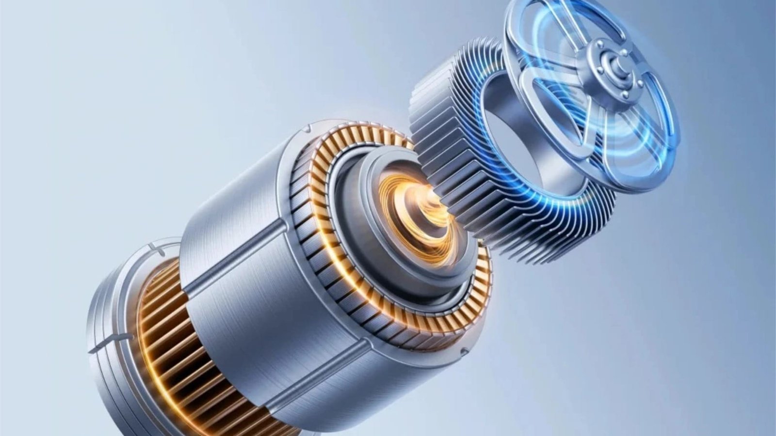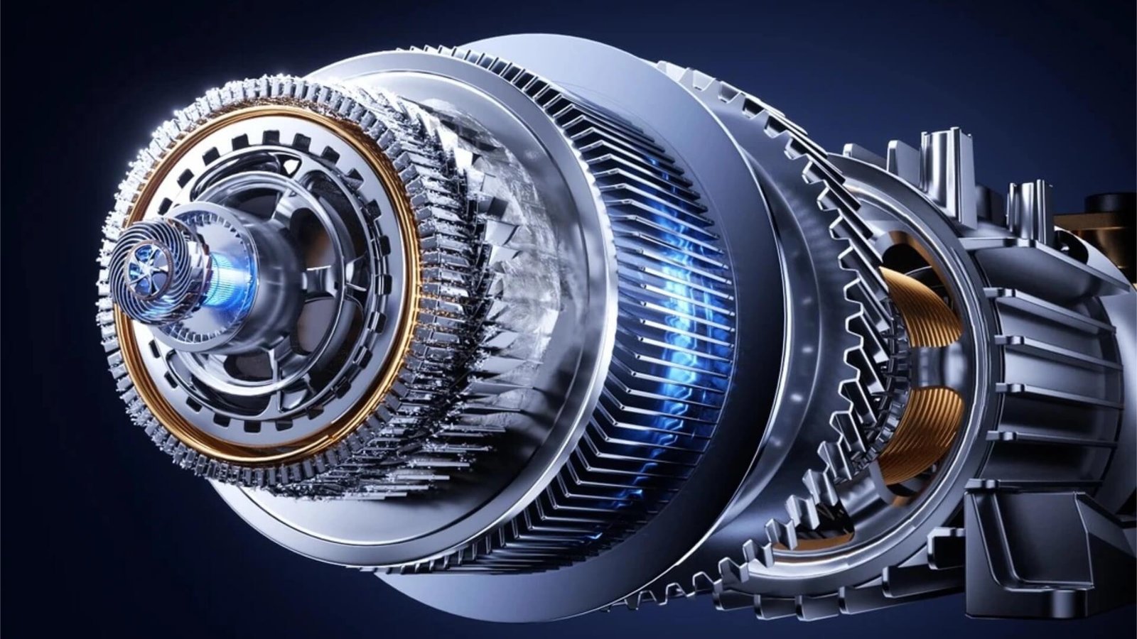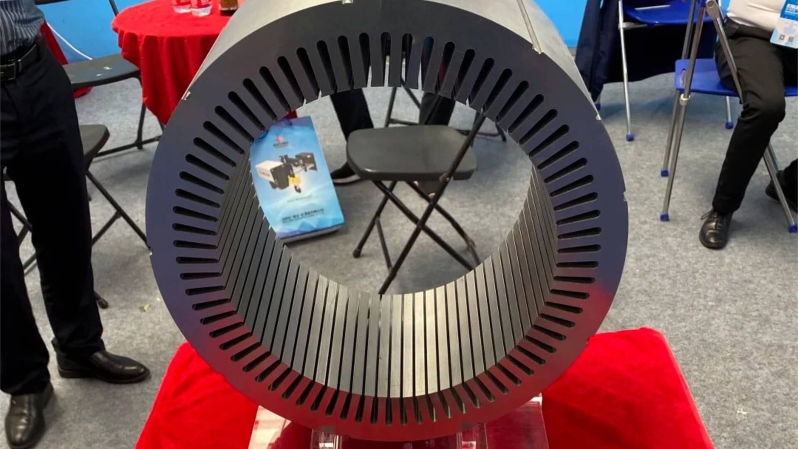
The drone revolution has transformed industries ranging from aerial photography and agricultural spraying to infrastructure inspection and military surveillance. At the heart of every unmanned aerial vehicle (UAV) — whether a 250-gram consumer quadcopter or a 25-kilogram industrial inspection platform — are the electric motors that generate lift, thrust, and control. And at the heart of every drone motor is a laminated core whose precision, weight, and magnetic performance directly determine flight time, payload capacity, and mission success.
Drone motor core dies represent the extreme edge of motor tooling technology. They must produce laminations from some of the thinnest silicon steel grades in volume production — 0.20mm and even 0.15mm — with tolerances measured in single-digit microns. They must support production speeds that reach 600–800 strokes per minute, all while maintaining the edge quality and dimensional stability required for motors that spin at 10,000 to 50,000 RPM. And they must do all this in a package so small that the entire die might fit on a desktop.
This article examines the unique challenges and specialized solutions for drone and UAV motor core stamping dies. Whether you are developing a new propulsion platform for a commercial UAV or scaling production of consumer drone motors, this guide provides the technical foundation needed to source effective tooling. Visit our Drone & UAV Motor solutions page for additional context on our capabilities in this demanding segment.
1. The Rise of Drone Motors and Their Extreme Tooling Demands
The global drone market has experienced explosive growth over the past decade. Consumer drones have become mainstream products; commercial UAVs are transforming agriculture, construction, energy, and logistics; and military drones have become essential defense assets. Each of these segments demands motors that push the boundaries of what is physically possible.
Drone motors operate under constraints that are extreme by any standard:
- Minimal weight: Every gram of motor mass reduces flight time. Drone motor designers relentlessly shave weight from every component — including the laminated core, which must use the thinnest available silicon steel to minimize both weight and core losses.
- Extreme speed: Drone motors typically operate at 10,000–50,000 RPM, far exceeding the speeds of most other motor types. These speeds demand exceptional rotor balance, which in turn requires lamination stacks with near-perfect concentricity and uniformity.
- High efficiency at partial load: Drones spend much of their flight time at partial throttle. Motor efficiency across the entire operating range is critical for maximizing flight endurance, placing a premium on core quality and magnetic performance.
- Rapid product cycles: The drone industry moves at consumer-electronics speed. New motor designs appear every 6–12 months, requiring tooling lead times that are compressed compared to other motor segments.
These demands create a tooling environment where precision, speed, and agility are not just desirable — they are mandatory. At ZHIXIANG, our die design and engineering team has developed specialized capabilities for the ultra-thin-gauge, ultra-high-speed stamping required by drone motor manufacturers.
2. Key Characteristics of Drone and UAV Motor Cores
Drone motor cores are the smallest and thinnest of any motor category. Understanding their defining characteristics is essential for effective die design.
Size range and geometry
Drone motors are compact. Typical dimensions:
| Drone Category | Stator OD | Rotor OD | Stack Height | Slot Counts |
|---|---|---|---|---|
| Micro (sub-250g) | 15–25mm | 10–18mm | 3–8mm | 9–12 slots |
| Small consumer | 25–40mm | 15–25mm | 5–15mm | 12–18 slots |
| Commercial/industrial | 40–60mm | 25–40mm | 10–25mm | 18–24 slots |
| Heavy-lift / special | 60–80mm | 35–55mm | 15–35mm | 24–36 slots |
The tiny dimensions mean that die components are correspondingly small — punches as narrow as 0.8mm, die inserts smaller than a coin. This miniaturization pushes the limits of precision manufacturing and creates unique challenges in component handling, alignment, and maintenance.
Silicon steel grades and thicknesses
Drone motors use the thinnest silicon steel in volume production:
| Drone Category | Typical Thickness | Common Grades |
|---|---|---|
| Consumer standard | 0.27mm | 27A230, M270-27A |
| Consumer premium | 0.20mm | 20A1500, 20WTG1500 |
| High-performance commercial | 0.20mm | 20A1500 |
| Experimental / racing | 0.15mm | 15A1800 (specialty) |
At 0.20mm and below, the stamping challenges are extreme. The material is less than one-quarter the thickness of a human hair, and even a burr of 0.005mm represents 2.5% of material thickness. Our article on silicon steel grade and insulation coating impact provides detailed guidance on thin-gauge stamping considerations.
Slot geometry and special features
Drone motor stators feature:
- Extremely narrow teeth: Often 0.8–1.5mm wide, requiring punches of similar width.
- High slot counts for small diameters: 12–24 slots in a 25–40mm diameter is common, compressing the geometry into a very small space.
- Precise slot symmetry: For smooth torque output and minimal vibration at extreme speeds, slot-to-slot spacing must be uniform within microns.
- Skewed slots or poles in some premium designs to minimize cogging torque.
Stacking methods
Drone motor cores use specialized stacking approaches:
- Gluing (self-adhesive bonding): The dominant method for drone motors. Bonded cores offer full electrical isolation, critical for minimizing losses at the high frequencies (400–800 Hz) at which drone motors operate. The die must produce flat, adhesive-ready surfaces without interlocking dimples.
- Interlocking: Used in some consumer applications where the motor design tolerates the small efficiency penalty. Interlocking dimples on 0.20mm material require extremely precise forming to avoid tearing.
- Loose lamination stacking: Rare, but used in some experimental designs where the core is assembled with external fixtures.
The dominance of gluing means that drone motor dies place exceptional emphasis on surface flatness and edge cleanliness — any burr or surface irregularity interferes with adhesive bonding and degrades motor performance. Our article on EV motor core die design covers the interlocking versus gluing trade-off in depth, and the principles apply even more strongly to drone applications.
3. The Extreme Demands of Drone Motor Cores
Drone motor cores represent the convergence of several extreme requirements, each pushing the boundaries of stamping technology.
Ultra-high speed operation
Drone motors rotate at speeds unmatched by other motor categories:
| Motor Type | Typical Operating Speed |
|---|---|
| Drone (small consumer) | 10,000–20,000 RPM |
| Drone (commercial) | 8,000–15,000 RPM |
| Drone (racing) | 20,000–50,000 RPM |
| Power tool (comparison) | 15,000–30,000 RPM |
| EV traction (comparison) | 8,000–20,000 RPM |
| Industrial (comparison) | 1,000–4,000 RPM |
At 30,000 RPM, the rotor spins 500 times per second. This demands exceptional rotor balance — any eccentricity, even a few microns, generates centrifugal forces that cause vibration, bearing wear, and in extreme cases, catastrophic failure. The laminated core’s concentricity and uniformity are the foundation of this balance.
Ultra-lightweight construction
For a drone, weight translates directly to flight time. A motor that is 10 grams lighter might add 30–60 seconds of hover time — significant in a market where every second counts.
The laminated core’s weight is determined by:
- Material thickness: Thinner silicon steel means less iron for a given stack height. The industry’s shift from 0.35mm to 0.20mm is driven primarily by weight reduction.
- Stacking factor: A higher stacking factor means more iron in the same volume, reducing core length and weight for equivalent magnetic performance.
- Design optimization: Minimizing tooth width and yoke thickness while maintaining structural integrity and magnetic performance.
The die’s role is to enable these lightweight designs by producing laminations with the precision required for thin sections and high stacking factors.
Ultra-thin material stamping
The 0.20mm silicon steel used in premium drone motors represents the limit of practical volume stamping. At this thickness:
- Optimal clearances are microscopic: 3–4% of material thickness per side translates to 0.006–0.008mm — less than 10 microns. Maintaining such clearances uniformly across a multi-station die demands exceptional manufacturing precision.
- Edge quality is paramount: Any burr, rollover, or edge damage is proportionally larger relative to the material thickness, magnifying its impact on motor performance.
- Punch deflection is critical: Slender punches must deflect less than 0.001mm under load to maintain clearance uniformity. This effectively mandates carbide punches with fully guided strippers.
- Thermal effects are amplified: The small thermal mass of both the material and the die means that frictional heat builds quickly and affects clearances rapidly. Thermal compensation is essential.
Our article on reducing burr height in motor lamination stamping provides detailed guidance on thin-gauge burr control, and our article on high-speed stamping die design optimization covers the thermal management strategies essential for ultra-thin materials.
High-frequency efficiency
Drone motors operate at high electrical frequencies because of their extreme rotational speeds and pole counts. A 14-pole motor spinning at 12,000 RPM experiences a fundamental electrical frequency of approximately 1,400 Hz — far higher than the 50–400 Hz typical of other motor types.
At these frequencies, core losses become the dominant efficiency-limiting factor:
- Hysteresis losses scale linearly with frequency.
- Eddy current losses scale with the square of both frequency and material thickness.
This is why thin (0.20mm) and ultra-thin (0.15mm) materials are essential — they reduce eddy current losses dramatically. But the stamping process must not reintroduce losses through burrs, edge damage, or interlaminar shorts. The die’s edge quality directly affects the motor’s high-frequency efficiency.
4. Unique Design Challenges in Drone Motor Core Dies
Ultra-thin material burr control and edge quality
At 0.20mm thickness, burr control reaches a new level of difficulty. The acceptable burr height for a drone motor lamination is typically ≤0.008mm — about one-third the thickness of a piece of paper. Achieving this over millions of strokes requires:
- Optimal clearances in the 3–4% range: For 0.20mm material, that’s 0.006–0.008mm per side. Even a clearance variation of 0.002mm can significantly affect burr height.
- Razor-sharp cutting edges: Only sub-micron carbide with excellent edge retention can maintain the sharpness required over 100 million strokes.
- Fully guided strippers: Punch deflection at these clearances is catastrophic. The stripper must provide continuous, zero-play guidance throughout the stroke.
- DLC or similar ultra-low-friction coatings: Prevent material adhesion that would quickly degrade edge quality.
Our article on reducing burr height in motor lamination stamping provides comprehensive strategies, all of which apply to drone motor dies in their most demanding form.
Extremely slender punch strength and guidance
Drone motor stator teeth can be as narrow as 0.8mm — thinner than a standard pencil lead. The punches that form these teeth have length-to-width ratios of 15:1 or even 20:1, pushing the limits of punch stability.
Managing these extremely slender punches requires:
- Ultra-fine-grained carbide punch material (0.2–0.5µm WC grain) for maximum stiffness and edge retention.
- Stepped punch designs with the thinnest section only at the cutting tip.
- Multi-level guided strippers providing support at multiple points along the punch length.
- Precision alignment between punch, stripper guide, and die opening — often verified with laser alignment during assembly.
- Specialized handling procedures during assembly and maintenance, as these micro-punches are easily damaged.
Our article on BLDC motor core die design covers slender punch management in detail, and drone motor dies represent the extreme case of these challenges.
Thermal management in miniature dies
The small size of drone motor dies creates paradoxical thermal challenges:
- Low thermal mass: The die heats up quickly because there is little material to absorb heat.
- High cutting frequency: At 600 SPM, frictional heat is generated continuously.
- Tight clearances: Even small thermal expansions alter clearances proportionally more than in larger dies.
Managing these effects requires:
- Carbide cutting edges with high thermal conductivity to dissipate heat rapidly.
- MQL lubrication for evaporative cooling at the cutting interface.
- Directed air cooling for continuous convective heat removal.
- Thermal compensation calculations accounting for the expected operating temperature rise.
The principles are discussed in our article on high-speed stamping die design optimization, with specific application to miniature dies.
Vibration control at extreme speeds
Drone motor dies often operate at 500–800 SPM — the highest stamping speeds in the motor industry. At these speeds, vibration control is paramount:
- Die natural frequency must remain well above the operating frequency to avoid resonance. The small, stiff structure of drone dies is advantageous here.
- Zero-play guidance is essential — any play in the guide system becomes amplified at high cycling rates.
- Balanced punch forces across the die face prevent dynamic instability.
- Precision strip feeding minimizes strip vibration at the die entry.
Our article on high-speed stamping die design optimization provides comprehensive vibration control strategies applicable to drone motor dies.
Extreme stack height precision
Drone motor stack heights are tiny — often 3–15mm — requiring exceptionally precise stack height control. A variation of ±0.02mm in a 5mm stack represents a 0.4% error, which affects motor performance and assembly consistency.
For glued stacks, the die must produce laminations with:
- Exceptional flatness: Any camber or edge wave in individual laminations accumulates in the stack.
- Clean, adhesive-compatible surfaces: No burrs, scratches, or contaminants that would interfere with bonding.
- Consistent thickness: Laminations of uniform thickness ensure predictable stack height.
These requirements make drone motor dies among the most demanding precision tools in the stamping industry.
5. Tool Material and Coating Selection for Drone Motor Dies
For drone motor dies, material and coating selection is driven by the extreme precision requirements.
Tungsten carbide: The only rational choice
For cutting components in drone motor dies, tungsten carbide is not an upgrade — it is the baseline requirement. The ultra-thin materials and ultra-tight clearances simply cannot be maintained with tool steel punches.
The preferred carbide grades are:
- Ultrafine grain (0.2–0.5 µm WC): For the thinnest, most demanding applications. These grades offer the highest hardness and best edge retention, essential for 0.20mm material.
- Sub-micron grain (0.5–0.8 µm WC): For slightly less demanding stations and for applications where some added toughness is beneficial.
- Cobalt content of 6–8%: Balances hardness with sufficient toughness to resist micro-chipping under high-speed cyclic loading.
Our tungsten carbide stamping die page provides comprehensive information on our carbide technology and its applications in extreme-precision stamping.
DLC coating: Essential for drone motor applications
DLC (Diamond-Like Carbon) is the coating of choice for drone motor die cutting components. Its properties are uniquely suited to the demands of ultra-thin stamping:
- Ultra-low friction (0.05–0.10): Minimizes heat generation and prevents material adhesion — critical for thin-gauge stamping.
- Exceptional hardness (2500–5000 HV): Resists the abrasive wear of silicon steel coatings.
- Chemical inertness: Prevents adhesion of silicon steel particles and lubricant residues.
- Low deposition temperature: Compatible with carbide substrates without thermal damage.
At ZHIXIANG, DLC coating on carbide punches is the standard specification for drone motor die cutting components. Our article on advanced surface treatments for motor core dies provides comprehensive information on DLC and other coating options.
TiAlN for selected stations
For stations where thermal stability is more critical than friction reduction — such as high-speed notching operations — TiAlN may be specified in place of or in addition to DLC. Its aluminum oxide layer provides superior thermal protection at the elevated temperatures of high-speed stamping.
Complete material and coating specification
| Component | Material | Coating | Rationale |
|---|---|---|---|
| Stator slot punches | Ultrafine carbide (WC-6Co) | DLC | Extreme thinness, minimal adhesion |
| Rotor pole punches | Ultrafine carbide (WC-6Co) | DLC | Same as above |
| Die inserts (cutting) | Sub-micron carbide (WC-8Co) | TiAlN | Abrasive resistance |
| Stripper guide inserts | Sub-micron carbide (WC-8Co) | DLC | Low friction guidance |
| Guide posts/bushings | Bearing steel | CrN | Anti-galling at high frequency |
| Die plates | Tool steel (DC53) | — | Structural support |
| Punch retainers | Tool steel (D2) | — | Structural support |
6. Progressive Die Design for Drone Motor Cores
Drone motor cores are produced using a motor core progressive die, with the progressive architecture offering the necessary speed, precision, and integration capability. However, drone motor dies require specialized design approaches due to their miniature size and extreme precision requirements.
Strip layout and station arrangement
A typical drone motor progressive die follows this sequence:
- Piloting and pre-piercing: Pilot holes for precise strip positioning, rotor shaft holes.
- Rotor slot notching: Rotor slots cut progressively over 2–3 stations.
- Stator slot cutting: Stator slots cut over 3–4 stations, progressively forming the narrow teeth.
- Rotor blanking: Rotor blanked from the strip. For glued rotors, the blanking station must produce clean, flat surfaces.
- Stator blanking: Finished stator blanked with extreme edge quality.
- Separate stacking: For glued stacks, the laminations are collected and stacked with adhesive application in a separate operation. For interlocked stacks, the die includes stacking stations.
The exact station count depends on the slot count and feature density. A 12-slot drone stator might use 8–10 stations; a 24-slot design might use 14–18 stations — all within a die that might be only 300–400mm in length.
Gluing-compatible surface requirements
Since most drone motor cores use glued stacks, the die must produce laminations with surfaces optimized for adhesive bonding:
- Flatness: Laminations must be perfectly flat to ensure uniform adhesive distribution.
- Edge cleanliness: No burrs or edge damage that would interfere with bonding.
- Surface cleanliness: No oil or contamination that would prevent adhesion.
- Consistent thickness: Uniform material thickness ensures predictable adhesive layer thickness.
These requirements mean that drone motor dies often use minimal lubrication (or dry stamping with MQL) to avoid surface contamination. Our article on EV motor core die design covers the gluing process and its tooling implications in detail.
Micro-punch design and manufacturing
The punches used in drone motor dies are among the smallest precision components in the stamping industry. Designing and manufacturing these micro-punches requires:
- Specialized carbide grades with ultrafine grain structure for maximum strength and edge retention.
- Precision wire EDM capable of cutting profiles with ±0.001mm accuracy at sub-millimeter dimensions.
- Jig grinding for final sizing of critical features.
- CMM inspection with probe tips small enough to measure sub-millimeter features.
- Specialized handling and assembly procedures to prevent damage to fragile components.
Our precision manufacturing team has developed specialized expertise in micro-punch manufacturing for drone motor applications.
Quick-change systems in miniature dies
Even the smallest drone motor dies benefit from quick-change punch systems. However, implementing quick-change features in miniature dies presents unique challenges:
- Limited space: Ball-lock retainers and quick-change mechanisms require space that may not be available in a miniature die.
- Tiny components: The quick-change components themselves must be miniaturized, increasing manufacturing complexity.
- Precision retention: Quick-change systems must not compromise punch alignment, which is critical at these tolerances.
At ZHIXIANG, we have developed quick-change solutions specifically for miniature dies, enabling rapid maintenance while preserving the precision required for drone motor production.
7. Achieving Precision at the Limits of Thin-Gauge Stamping
Drone motor dies operate at the very edge of what is achievable in volume stamping. Achieving and maintaining the required precision demands the highest level of engineering discipline.
Clearance optimization for 0.20mm material
For 0.20mm silicon steel, the optimal clearance is 3–4% of material thickness per side — 0.006–0.008mm. At these dimensions:
- Manufacturing tolerance must be ±0.001mm or better: Any deviation significantly affects the clearance ratio.
- Assembly alignment must be verified with laser precision: Traditional alignment methods are insufficient at these tolerances.
- Thermal compensation is critical: The expected operating temperature rise must be calculated and compensated for in the cold clearance specification.
Thermal compensation calculations
The thermal behavior of miniature dies must be modeled and compensated:
- Heat input: Calculated from cutting forces, speeds, and material properties.
- Temperature distribution: Modeled using thermal simulation, accounting for die mass, thermal conductivity, and cooling effects.
- Dimensional changes: Calculated from the temperature distribution and material thermal expansion coefficients.
- Cold clearance specification: Adjusted so that the running clearance at operating temperature matches the optimal value.
Our article on high-speed stamping die design optimization provides detailed guidance on thermal compensation methodology.
Burr height standards for drone motors
Drone motor lamination burr height standards are the tightest in the motor industry:
| Material Thickness | Max Burr Height | % of Material Thickness |
|---|---|---|
| 0.20mm | 0.006mm | 3.0% |
| 0.27mm | 0.008mm | 3.0% |
| 0.35mm | 0.010mm | 2.9% |
Achieving these standards requires the combination of ultra-fine carbide, DLC coatings, fully guided strippers, and meticulous maintenance discipline. Our article on reducing burr height in motor lamination stamping provides comprehensive measurement and control strategies.
Concentricity and dynamic balance
At 30,000 RPM, rotor balance is critical. The laminated core’s concentricity and uniformity directly affect dynamic balance:
- Rotor OD concentricity to shaft bore: Must be within ±0.005mm for high-speed drone motors.
- Slot uniformity: Slot-to-slot spacing variation must be within microns to ensure magnetic balance.
- Stack alignment: Laminations must be perfectly aligned in the stack to prevent imbalance.
These requirements place extreme demands on die precision and consistency. Our quality control team verifies these parameters on every drone motor die we build.
8. Case Example: Drone BLDC Motor Core Die for a Commercial UAV
To illustrate these principles in practice, consider a recent drone motor core die project for a commercial inspection UAV:
Motor specifications:
- Stator OD: 35mm
- Rotor OD: 22mm
- Stator slots: 18
- Rotor poles: 16
- Silicon steel: 0.20mm 20A1500 (3.0% Si)
- Insulation coating: C3 organic
- Stacking: Glued stack (no interlocking)
- Air gap requirement: 0.25mm ±0.015mm
- Burr requirement: ≤0.006mm
- Motor speed: 12,000 RPM
- Production volume: 1.5 million motors/year
- Target stamping speed: 600 SPM
Die specifications:
| Parameter | Specification | Rationale |
|---|---|---|
| Die type | Progressive die, 14 stations | High speed, complex geometry |
| Die set size | 350mm × 300mm | Miniature die |
| Cutting components | Ultrafine tungsten carbide (WC-6Co) | Extreme edge retention |
| Punch coating | DLC on all cutting punches | Ultra-low friction, anti-adhesion |
| Die insert coating | TiAlN | Thermal stability |
| Guidance | Ball-bearing guides + multi-level guided stripper | Zero-play, multi-point support |
| Clearance (cold) | 0.007mm per side (3.5% t, thermally compensated) | Optimal running clearance |
| Lubrication | MQL vanishing oil, 3 ml/hour | Minimal residue for gluing |
| Cooling | Directed air at 3 bar pressure | Convective cooling |
| Stacking | Glue-compatible flat surfaces | Premium efficiency design |
Performance results:
| Metric | Result |
|---|---|
| First tryout burr height | 0.002–0.004mm |
| Burr height at 30M strokes | 0.003–0.005mm |
| Air gap concentricity | 0.009mm (requirement ≤0.015mm) |
| Slot width variation | ±0.002mm |
| Lamination flatness | ≤0.005mm |
| Motor efficiency | 91.3% (target ≥90%) |
| Motor noise | 38 dB(A) at 1m (target ≤42) |
| First regrind | At 60 million strokes |
| Total projected die life | >200 million strokes |
This project — representative of our work with Drone & UAV Motor customers — demonstrates that drone motor core dies can achieve the extreme precision required for high-speed flight while maintaining production speeds and tool life that make economic sense. The die delivered burr heights below 0.005mm consistently and concentricity better than the design requirement, contributing to a motor that exceeded its efficiency and noise targets.
Similar results have been achieved across the full range of drone applications — from micro consumer drones to heavy-lift commercial platforms. The underlying engineering principles remain consistent; only the specific parameters change with each application.
9. Conclusion: Partnering for Drone Motor Core Tooling Success
Drone motor core dies represent the cutting edge of motor tooling technology. The combination of ultra-thin materials (0.20mm and below), extreme precision requirements (single-digit micron tolerances), and high production speeds (600+ SPM) creates a tooling challenge that few manufacturers can meet.
At ZHIXIANG (motordie.com), we have invested in the specialized capabilities required for drone motor applications: ultrafine carbide materials, DLC coating technology, micro-punch manufacturing expertise, and the precision assembly and verification processes needed to maintain clearances at the micron level. Our die design and engineering team understands the unique demands of aerial propulsion motors, our precision manufacturing capabilities deliver components with sub-micron accuracy, and our quality control process verifies every dimension and every edge before delivery.
Whether you are developing motors for consumer quadcopters, commercial inspection UAVs, or specialized defense platforms, we have the experience and capability to deliver the precision tooling you need to compete at the highest level.
Ready to push the limits of drone motor performance? Send us your lamination drawing, silicon steel specification, and production requirements. Our engineering team will provide a detailed technical proposal — including material selection, coating recommendations, and tolerance analysis — within 48 hours. Send your drawing today and let’s build the tooling foundation for your next-generation drone propulsion platform.