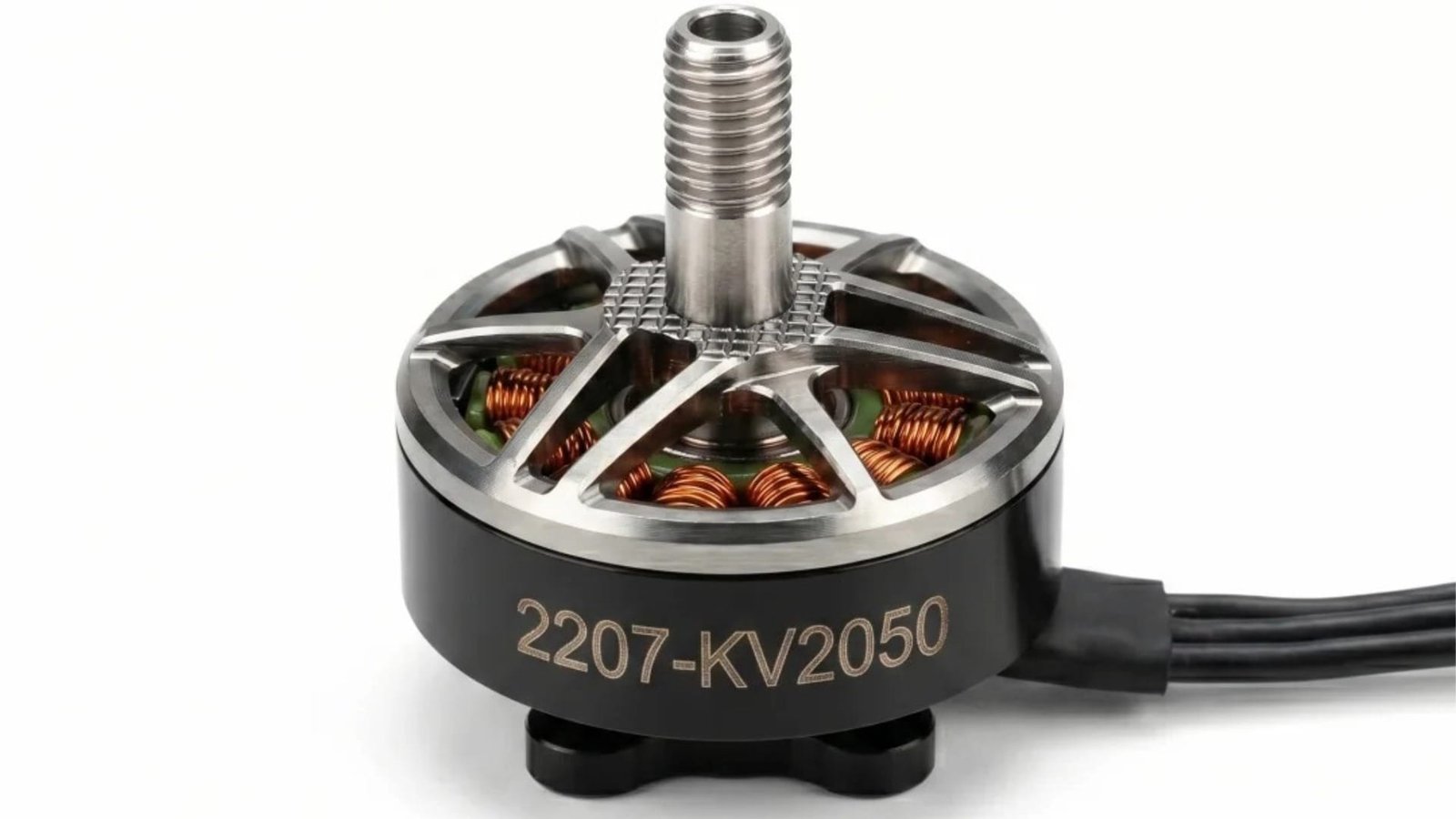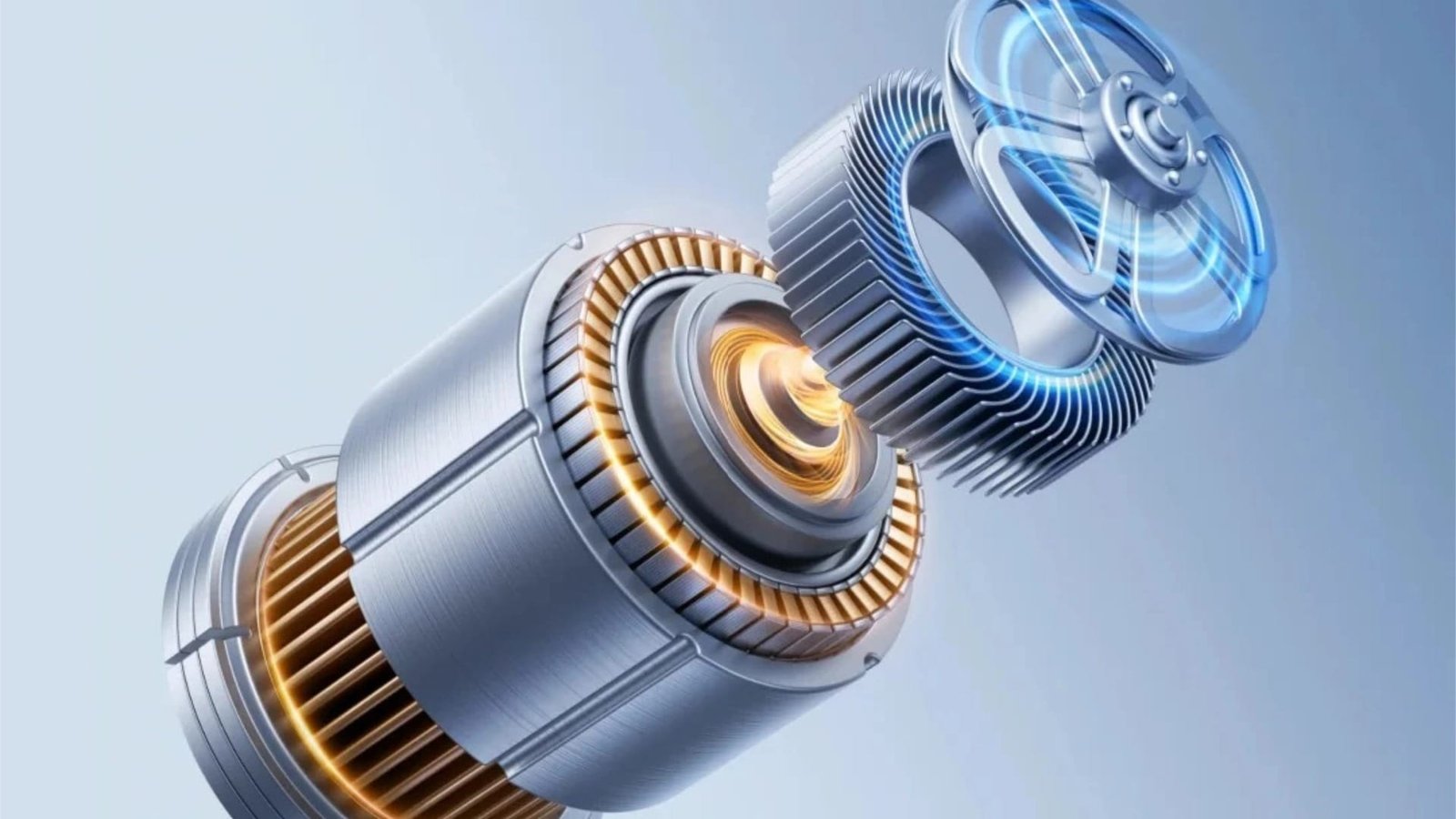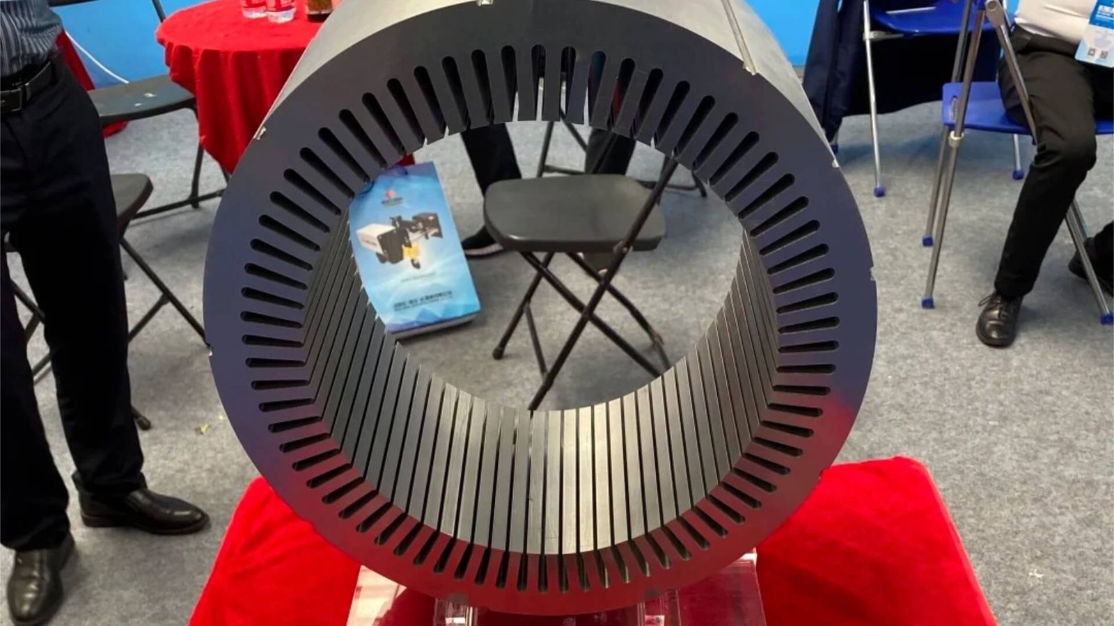
The power tool industry is one of the largest and most dynamic segments of the global motor market. From cordless drills and impact drivers to circular saws, angle grinders, and rotary hammers, power tools are produced in staggering volumes — hundreds of millions of units annually worldwide. Each of those tools contains at least one electric motor, and at the heart of every motor is a precision-stamped laminated core.
Power tool motor cores present a unique tooling challenge. They are compact — typically 40–80mm stator outer diameter — yet demand high precision to minimize noise, vibration, and energy loss. They are produced at extremely high speeds — 400–600 strokes per minute or more — yet must maintain tight tolerances over production runs measured in hundreds of millions of cycles. And they operate in a fiercely cost-competitive market, where tooling economics directly determine product profitability.
This article examines the design challenges, material considerations, and proven solutions for power tool motor core stamping dies. Whether you are developing a new cordless BLDC platform or optimizing an existing corded universal motor line, this guide provides the technical foundation you need to source effective tooling. For additional context on our capabilities in this segment, visit our Power Tools Motor solutions page.
1. The Power Tool Industry and Its Tooling Demands
The power tool market has undergone a fundamental transformation over the past two decades. The shift from corded to cordless tools has accelerated dramatically, driven by advances in lithium-ion battery technology, brushless DC motor efficiency, and consumer demand for portability. Today, cordless tools account for the majority of premium power tool sales, and even traditionally corded categories — circular saws, angle grinders, miter saws — are rapidly transitioning to battery power.
This transformation has profound implications for motor core tooling. The older corded tools predominantly used universal motors (series-wound brushed motors) operating at very high speeds — 20,000 to 30,000 RPM. These motors use relatively simple laminated cores, often with 12–16 slots, and are less demanding of precision. Their production volumes remain substantial, particularly in cost-sensitive markets.
The newer cordless tools use brushless DC (BLDC) motors, which offer significantly higher efficiency, longer runtime, and better controllability. BLDC power tool motors demand tighter tolerances, better air gap concentricity, and often use thinner silicon steel (0.27–0.35mm) to minimize high-frequency core losses. Their production volumes are enormous — a single popular cordless drill platform may require tens of millions of stator laminations per year.
The tooling implications are clear: power tool motor core dies must deliver precision, speed, and longevity in equal measure. They must be designed for the specific motor type — universal or BLDC — and optimized for the production environment. This is where our die design and engineering expertise becomes essential.
2. Key Characteristics of Power Tool Motor Cores
Power tool motor cores share several defining characteristics that shape die design decisions.
Size and geometry
Power tool motors are compact. Typical dimensions:
| Tool Category | Stator OD | Rotor OD | Stack Height | Common Slot Counts |
|---|---|---|---|---|
| Small cordless (drill, driver) | 40–50mm | 20–28mm | 20–40mm | 6–12 slots |
| Medium cordless (saw, grinder) | 50–65mm | 25–35mm | 30–50mm | 12–18 slots |
| Corded universal | 50–70mm | 28–40mm | 30–60mm | 12–16 slots |
| High-power cordless | 65–80mm | 32–45mm | 40–70mm | 18–24 slots |
The small size means die components are correspondingly small, with punches often 1.5–3mm wide and 15–25mm long. This miniaturization increases the difficulty of maintaining clearance and alignment, particularly at high stamping speeds.
Silicon steel grades and thicknesses
Power tool motors predominantly use medium-thin silicon steel:
| Motor Type | Typical Thickness | Common Grades |
|---|---|---|
| Corded universal (standard) | 0.50mm | 50A470, 50W470 |
| Corded universal (premium) | 0.35mm | 35A300, 35W300 |
| Cordless BLDC (standard) | 0.35mm | 35A300, 35W300 |
| Cordless BLDC (premium) | 0.27mm | 27A230, M270-27A |
The trend toward 0.27mm in premium cordless tools mirrors the broader industry shift toward thinner gauges for higher efficiency. Our article on silicon steel grade and insulation coating impact provides detailed guidance on how thickness and grade affect die design.
Slot geometry and special features
Power tool stator slots are characterized by:
- Narrow slot openings: To maximize winding area and minimize magnetic reluctance, slot openings are often just 1.5–2.5mm wide.
- Relatively deep slots: To accommodate sufficient copper windings in a small diameter, slots are proportionally deep — often 6–10 times their width.
- Small teeth: The teeth between slots are narrow, requiring precise punching to maintain structural integrity and magnetic performance.
- Skewed slots or poles: Some premium power tools use skewed rotors to reduce cogging torque and acoustic noise.
These features demand slender punches with robust guidance — the same challenges we discussed in our BLDC motor core die design article, though the scale is even smaller in power tool applications.
Stacking methods
Power tool motor cores use two primary stacking methods:
- Auto-interlocking (self-riveting): The dominant method for high-volume production. The die forms dimples that mechanically join laminations into a stack without secondary operations.
- Gluing (self-adhesive bonding): Increasingly used in premium BLDC power tools to maximize efficiency by eliminating interlaminar eddy currents at the interlocking points.
The choice affects die design significantly. Auto-interlocking requires dedicated forming stations and precise stack counting; gluing requires flat, adhesive-ready lamination surfaces without interlock dimples. We covered the interlocking versus gluing trade-off in our article on EV motor core die design, and the principles apply directly to power tool applications.
3. Corded vs. Cordless: Different Motor Types, Different Die Requirements
Power tool motor core dies are not one-size-fits-all. The motor type — universal (corded) or BLDC (cordless) — has a major impact on tooling requirements.
Corded universal motors
Universal motors are series-wound brushed motors that operate at very high speeds (20,000–30,000 RPM). Their laminated cores have several distinctive characteristics:
- Larger air gaps (typically 0.30–0.50mm) to accommodate the mechanical tolerances of high-speed operation.
- Fewer slots (12–16) with simpler geometry, reflecting the lower precision requirements.
- Thicker silicon steel (0.50mm) in many cost-sensitive applications.
- Welded or bolted stacking rather than auto-interlocking in many designs.
The die requirements for universal motor cores are less demanding in terms of precision but still require robust construction for high-volume production. Tool steel progressive dies remain common for this segment, with carbide reserved for high-volume applications.
Cordless BLDC motors
BLDC power tool motors represent a significant step up in precision requirements:
- Smaller air gaps (typically 0.20–0.35mm) to maximize torque density and efficiency.
- More slots (12–18, with some designs using 24) with tighter tolerance requirements.
- Thinner silicon steel (0.27–0.35mm) to reduce high-frequency core losses.
- Auto-interlocking or gluing for stack assembly, integrated into the die.
The die requirements for BLDC power tool cores are substantially more demanding. Tungsten carbide cutting components are standard for high-volume production, and the guidance systems must maintain zero-play alignment at high stamping speeds. Our BLDC motor core die design article provides a comprehensive treatment of these requirements.
The transition zone
Many power tool manufacturers produce both corded and cordless tools, and some motor platforms straddle the boundary — for example, a high-speed BLDC motor that replaces a universal motor in a cordless circular saw. The tooling strategy must accommodate this transition:
- Modular die designs that allow slot geometry changes without complete retooling.
- Material upgrades from tool steel to carbide as production volumes and precision requirements increase.
- Flexible stacking options — dies that can produce either interlocked or flat gluing-compatible laminations.
At ZHIXIANG, we work with power tool manufacturers across the full spectrum — from cost-optimized universal motor dies to premium BLDC tooling with carbide cutting edges and DLC coatings. This breadth of experience allows us to match the tooling specification precisely to the motor type and production requirements.
4. Design Challenges in Power Tool Motor Core Dies
Power tool motor core dies face several demanding challenges that must be addressed through careful design.
High-speed stamping: vibration and thermal management
Power tool motor laminations are produced at the highest stamping speeds in the motor industry — commonly 400–600 SPM, with some operations pushing toward 800 SPM. At these speeds, vibration and heat generation become critical concerns.
Vibration: The die structure’s natural frequencies must remain well above the operating frequency to avoid resonance. The small size of power tool dies is advantageous here — their compact, stiff structure naturally has higher natural frequencies than larger dies. However, the guidance system must still eliminate all play to prevent micro-vibration at high cycling rates.
Thermal management: Frictional heat at 600 SPM accumulates rapidly. The die must be designed with effective cooling — carbide cutting edges for thermal conductivity, MQL lubrication for evaporative cooling, and directed air blasts for convective cooling. Our article on high-speed stamping die design optimization covers these strategies in comprehensive detail.
Slender punch guidance and support
The narrow slots and small teeth of power tool stators require punches with very small cross-sections — often 1.5–2.5mm wide and 15–25mm long. These slender punches are highly susceptible to buckling and vibration at high stamping speeds.
The solutions are the same as those we detailed in our BLDC motor core die design article:
- Stepped punch designs with larger bodies and only the working tip at final size.
- Fully guided strippers with hardened, replaceable guide inserts.
- Carbide punch material for maximum stiffness and minimal deflection.
- Careful punch length optimization to minimize unsupported length.
In power tool applications, these measures are even more critical due to the extreme stamping speeds involved.
Noise and vibration control
Power tool noise is a critical quality parameter — particularly for professional-grade tools where operator comfort and workplace safety are paramount. Motor noise originates from multiple sources:
- Cogging torque from magnetic asymmetry in the motor core, directly related to lamination precision.
- Mechanical imbalance from rotor eccentricity, amplified by the tool’s high operating speed.
- High-frequency electromagnetic noise from the interaction of stator and rotor harmonics.
The die’s role in noise control is to produce laminations with consistent geometry, minimal dimensional variation, and precise stacking alignment. Uneven slots, inconsistent air gap, or misaligned stacks all contribute to increased noise and vibration.
High-volume production and die longevity
Power tool motor production volumes are among the highest in the motor industry. A single popular cordless drill platform may produce 10 million units annually, requiring 20 million stator laminations per year. Over a five-year product life, that’s 100 million laminations — demanding a die life of 100 million strokes or more with minimal downtime.
This requires:
- Premium tool materials — tungsten carbide cutting components as standard for high-volume BLDC production.
- Optimized maintenance schedules based on burr height and wear trend data.
- Quick-change punch systems that allow component replacement during brief production pauses.
- Spare parts availability to minimize downtime.
Our articles on extending motor lamination die life and preventive maintenance provide detailed guidance on maximizing tool longevity in high-volume applications.
5. Tool Material and Coating Selection for Power Tool Motor Dies
Material selection is decisive for power tool motor core dies, given the combination of high speed, high volume, and demanding precision.
Tungsten carbide for cutting components
For high-volume cordless BLDC production, sub-micron grain tungsten carbide is the standard for all cutting punches and die inserts:
- Wear resistance against abrasive silicon steel coatings at high speeds.
- Stiffness to prevent deflection of slender punches.
- Thermal stability to maintain hardness at the elevated temperatures of high-speed stamping.
- Dimensional stability to maintain clearances through thermal cycling.
Our tungsten carbide stamping die page details our carbide technology and its applications in high-speed motor core tooling.
PM tool steel for medium-volume and corded applications
For corded universal motor dies and medium-volume cordless applications, powder metallurgy tool steels like ASP23 and VANADIS 4 offer a cost-effective balance:
- Good wear resistance for 0.50mm material at moderate speeds.
- Better toughness than carbide for impact resistance.
- Lower cost than carbide, particularly for larger components.
Coating strategies
The insulation coating on the silicon steel — typically C5 semi-organic for power tool materials — dictates the optimal die coating:
- DLC (Diamond-Like Carbon): Best for adhesive-prone coatings and ultra-thin materials. Its ultra-low friction prevents material pickup and reduces heat generation.
- TiAlN (Titanium Aluminum Nitride): Ideal for high-speed operation where thermal stability is critical. Provides excellent abrasive wear resistance.
- CrN (Chromium Nitride): A versatile option for medium-speed applications, balancing low friction with good hardness.
Our article on advanced surface treatments for motor core dies provides comprehensive coating selection guidance applicable to power tool applications.
Hybrid material strategies
For cost-sensitive power tool production, a hybrid approach is often optimal:
- Tungsten carbide for the highest-wear cutting punches (slot punches, rotor pole punches).
- PM tool steel for medium-wear components and structural parts.
- Conventional tool steel for die plates and other large structural elements.
This targeted approach delivers most of the performance benefits of all-carbide construction at 60–70% of the cost. Our article on motor core stamping die cost provides additional guidance on optimizing tooling investment.
6. Progressive Die Design for Power Tool Motor Cores
Power tool motor cores are almost exclusively produced using a motor core progressive die. The progressive architecture offers the speed, precision, and integration capability essential for high-volume power tool production.
Strip layout and station arrangement
A typical power tool progressive die follows this sequence:
- Piloting and pre-piercing: Pilot holes for precise strip positioning, rotor shaft holes, and any ventilation features.
- Rotor slot notching: Rotor slots cut progressively over 2–3 stations to reduce punch load and improve edge quality.
- Stator slot cutting: Stator slots cut over 3–4 stations, progressively forming the slot shape and tooth geometry.
- Rotor blanking and stacking: Rotor blanked from the strip, with auto-stacking if required.
- Stator blanking and stacking: Finished stator blanked and stacked, with interlocking dimples formed and stack height controlled.
The exact station count depends on the slot count and feature density. A 12-slot BLDC stator for a cordless drill might require 10–14 stations; a 24-slot design for a high-power circular saw might require 16–20 stations.
Quick-change punch systems
Power tool production runs 24/7 in many facilities, making maintenance efficiency critical. Quick-change punch systems allow worn punches to be replaced in minutes without removing the die from the press:
- Ball-lock punch retainers for rapid punch insertion and removal.
- Modular die insert designs that allow individual station replacement.
- Precision-ground spare components that drop in without adjustment.
These features minimize production downtime and keep the die running at peak performance. Our motor core progressive die service incorporates quick-change systems as standard for high-volume applications.
Auto-stacking station design
The auto-interlocking station is critical for power tool stator production. It must form interlocking dimples with precise depth and geometry, then stack the laminations with correct rotational alignment and stack height. Key design elements include:
- Optimized interlocking geometry for the specific material thickness and stacking force.
- Robust interlocking punches in carbide with appropriate cobalt content.
- Precision stack counting for consistent stack height.
- Rotational alignment features to maintain lamination orientation.
The reliability of the stacking system directly affects downstream productivity. A die that produces inconsistent stacks causes jams, misaligned assemblies, and production delays.
7. Balancing Speed, Cost, and Quality in Power Tool Motor Production
Power tool manufacturing is intensely cost-competitive. The tooling strategy must balance performance with economic considerations, delivering the precision and speed required without unnecessary cost.
The cost-quality balance
The power tool market spans a wide quality spectrum:
- Value-priced tools: Cost-optimized universal motors with 0.50mm material, tool steel dies, and standard tolerances.
- Professional-grade cordless: BLDC motors with 0.35mm material, carbide dies, and tighter tolerances.
- Premium brushless: High-performance BLDC with 0.27mm material, carbide dies with DLC coatings, and ultra-tight tolerances.
Each tier has a different tooling cost structure. The key is matching the die specification to the product positioning — not over-investing in precision the product doesn’t need, and not under-investing in quality that the market demands.
The speed-economics equation
Higher stamping speeds reduce per-part cost but require more expensive dies with better thermal management and vibration control. The optimal speed balances:
- Die cost (higher for high-speed capable designs)
- Production throughput (higher at increased speeds)
- Maintenance frequency (often higher at extreme speeds)
- Quality consistency (may degrade at very high speeds)
For most power tool applications, 400–600 SPM represents the sweet spot, delivering high throughput without excessive tooling cost or quality compromises. Our article on high-speed stamping die design optimization provides detailed guidance on finding this balance.
The longevity equation
Die longevity directly affects total cost per part. A carbide die that costs 2.5 times more than a tool steel equivalent but lasts 3 times longer delivers a lower cost per stroke — provided the production volume justifies the investment. For power tool motor cores produced in millions per year, the economics overwhelmingly favor carbide for high-volume BLDC applications.
The cost analysis framework in our article on motor core stamping die cost provides a structured approach to evaluating these trade-offs.
8. Case Example: BLDC Power Tool Motor Core Die for a Cordless Drill
To illustrate these principles in practice, consider a recent power tool motor core die project for a cordless drill application:
Motor specifications:
- Stator OD: 44mm
- Rotor OD: 22mm
- Stator slots: 12
- Rotor poles: 8
- Silicon steel: 0.35mm 35A300 (2.2% Si)
- Insulation coating: C5 semi-organic
- Stacking: Auto-interlocking, 6 dimples per stator lamination
- Air gap requirement: 0.30mm ±0.020mm
- Burr requirement: ≤0.012mm
- Production volume: 8 million motors/year
- Target speed: 500 SPM
Die specifications:
| Parameter | Specification | Rationale |
|---|---|---|
| Die type | Progressive die, 12 stations | High speed and integration for volume production |
| Cutting components | Sub-micron tungsten carbide (WC-8Co) | Wear resistance and stiffness at 500 SPM |
| Punch coating | DLC on all cutting punches | Low friction, anti-adhesion on C5 coating |
| Die insert coating | TiAlN | Thermal stability and abrasive resistance |
| Guidance | Ball-bearing guides + fully guided stripper | Zero-play at high speed |
| Clearance (cold) | 0.019mm per side (5.4% t, thermally compensated) | Optimal running clearance |
| Lubrication | MQL vanishing oil, 5 ml/hour | Minimal residue on small lamination |
| Quick-change | Ball-lock punch retainers at all stations | Rapid maintenance |
| Auto-stacking | 6-dimple interlocking with stack counter | Reliable stack control |
Performance results:
| Metric | Result |
|---|---|
| First tryout burr height | 0.004–0.007mm |
| Burr height at 50M strokes | 0.006–0.009mm |
| Air gap concentricity | 0.014mm (requirement ≤0.020mm) |
| Slot width variation | ±0.003mm |
| Stack height variation | ±0.04mm |
| First regrind | At 85 million strokes |
| Total projected die life | >250 million strokes |
| Production speed achieved | 500 SPM (design target achieved) |
This project — typical of our work with Power Tools Motor customers — demonstrates that power tool motor core dies can achieve exceptional precision at high speeds while maintaining long tool life. The combination of carbide cutting edges, DLC coatings, and precision guidance delivers consistent quality over hundreds of millions of strokes.
Similar results have been achieved across the full range of power tool applications: corded universal motor dies for circular saws, BLDC tooling for impact drivers, and high-power dies for professional-grade angle grinders. The underlying engineering principles remain constant; only the specific parameters change with each application.
9. Conclusion: Partnering for Power Tool Motor Core Tooling Success
Power tool motor core dies occupy a unique position in the motor tooling landscape. They combine the precision demands of compact BLDC motors with the speed requirements of high-volume consumer production and the cost pressures of a fiercely competitive market. Succeeding in this environment requires tooling that delivers precision, speed, and longevity — without excessive cost.
At ZHIXIANG (motordie.com), we have built power tool motor core dies for leading manufacturers around the world. Our die design and engineering team understands the unique challenges of high-speed compact tooling, our precision manufacturing capabilities ensure that every die component meets exacting tolerances, and our quality control process verifies performance before delivery.
Whether you are producing corded universal motor cores with tool steel dies or premium cordless BLDC laminations with carbide tooling, we have the experience and capability to deliver the tooling you need.
Ready to optimize your power tool motor core tooling? Send us your lamination drawing, silicon steel specification, and production requirements. Our engineering team will provide a detailed technical proposal — including die type recommendation, material selection, and tolerance analysis — within 48 hours. Send your drawing today and let’s build the tooling foundation for your next power tool platform.