Servo motors and stepper motors are the precision workhorses of modern automation. They drive the axes of CNC machine tools, position robotic arms with micron-level repeatability, and synchronize the movements of high-speed packaging lines. Their ability to deliver precise, controllable motion depends on one foundational component: the motor core. And the motor core, in turn, depends on the stamping die that produces its laminations.
Unlike general-purpose motors, servo and stepper motors demand laminations with exceptionally tight geometric tolerances. The air gap between stator and rotor must be nearly perfect to ensure smooth torque output and minimal cogging. Slot geometries must be precise to within microns to achieve consistent winding insertion and optimal magnetic flux distribution. And because these motors often operate in high-precision motion control applications, even the smallest deviation in lamination quality can translate into positioning errors, vibration, and reduced performance.
This article explores the unique design challenges and proven solutions for servo and stepper motor core stamping dies. Whether you are developing a new servo platform for industrial automation or refining an existing stepper motor design, the insights here will help you understand what it takes to achieve ultra-precision in high-volume production. For additional context on our dedicated tooling solutions for this segment, visit our Servo & Stepper Motor solutions page.
1. Why Servo and Stepper Motors Demand the Highest Precision Tooling
The performance of a servo or stepper motor is directly tied to the precision of its laminated core. These motors rely on a small, consistent air gap to generate smooth torque with minimal cogging. The stator slots must be uniform and accurately positioned to ensure balanced winding resistance and optimal magnetic circuit symmetry. Any variation in lamination dimensions — even a few microns — can create magnetic asymmetry that manifests as vibration, audible noise, and reduced positioning accuracy.
In industrial automation applications, these performance deviations are unacceptable. A CNC machine that cannot hold position within ±0.005mm will produce defective parts. A robotic arm that vibrates due to motor cogging cannot perform precision assembly. A stepper motor with inconsistent step angles will accumulate positioning errors that compound over time.
The tooling implications are clear: servo and stepper motor core dies must be designed and manufactured to a higher standard than general-purpose motor dies. The clearances, guidance systems, material choices, and quality control processes must all be elevated to achieve the required precision — not just at die tryout, but consistently over hundreds of millions of strokes. This is where our die design and engineering philosophy becomes essential.
2. Key Characteristics of Servo and Stepper Motor Cores
To design an effective servo or stepper motor core die, one must first understand the unique characteristics of these laminations.
Stator and rotor geometry
Servo and stepper motor stators typically feature:
- High slot counts: Servo motors commonly have 12, 18, 24, or even 36 slots, while stepper motors often use 8, 16, 50, or 100-pole designs. The high number of slots and poles requires a correspondingly high number of punch components, increasing die complexity.
- Narrow teeth and small slot openings: To maximize torque density while minimizing cogging, servo/stepper stators often have narrow teeth and small slot openings. These features require slender punches with extremely tight tolerances.
- Small air gaps: Precision motion control motors typically operate with air gaps of 0.15–0.35mm. The concentricity between stator inner diameter and rotor outer diameter must be held within microns to maintain uniform magnetic flux.
Common silicon steel grades and thicknesses
Servo and stepper motors typically use thin, high-grade silicon steel to minimize core losses and improve dynamic response:
| Application | Typical Thickness | Common Grades |
|---|---|---|
| High-precision servo | 0.20–0.27mm | 20A1500, 27A230 |
| Industrial stepper | 0.27–0.35mm | 27A230, 35A300 |
| Cost-optimized stepper | 0.35–0.50mm | 35A300, 50A470 |
The move toward thinner materials directly mirrors the trends we discussed in our article on silicon steel grade and insulation coating impact. Thinner gauges reduce eddy current losses but demand tighter clearances and more precise die construction.
Stacking methods
Both servo and stepper motor cores commonly use auto-interlocking for stator stacking, though some premium servo applications specify gluing for maximum magnetic performance. The choice affects die design significantly — we cover the interlocking versus gluing decision in depth in our article on EV motor core die design, and the same principles apply to precision motion control motors.
3. Design Challenges Unique to Servo/Stepper Motor Core Dies
While servo and stepper motor dies share many characteristics with other motor core dies, several challenges are more acute in this segment.
High slot counts and slender punches
A servo motor stator with 36 slots requires 36 individual slot punches, each with a cross-section that may be only 1–2mm wide and 15–30mm long. These slender punches are highly susceptible to buckling and vibration, particularly at higher stamping speeds. Managing dozens of such punches simultaneously — ensuring each is perfectly aligned, properly guided, and consistently sharp — is a significant engineering challenge.
The solution lies in precision-guided strippers, stepped punch designs, and premium materials like tungsten carbide. These strategies are discussed in detail in our article on BLDC motor core die design, which covers similar slender-punch challenges, and they apply equally to servo and stepper motor tools.
Ultra-precision air gap concentricity
The air gap in a servo motor is the critical magnetic interface. For a motor with a nominal air gap of 0.25mm, a concentricity error of just 0.03mm represents a 12% variation in magnetic flux distribution — enough to cause measurable cogging and torque ripple. Achieving concentricity within ±0.01mm or better requires exceptional control of every station in the progressive die.
This is where our precision manufacturing capabilities become indispensable. By using slow-wire EDM and jig grinding to produce die components with sub-micron accuracy, and by assembling and verifying the die using CMM and laser alignment, we ensure that every station is positioned relative to a common datum within the tightest tolerances. The result is a die that produces laminations with consistent, ultra-precise concentricity from the first stroke to the hundred millionth.
Thin-gauge stamping burr and edge quality control
As with other precision motor types, servo and stepper motor laminations often use silicon steel as thin as 0.20mm. At this thickness, burr control becomes critical. Even a burr of 0.008mm represents 4% of material thickness — enough to affect stacking factor and interlaminar losses. Our article on reducing burr height in motor lamination stamping provides a comprehensive treatment of burr control strategies, all of which apply directly to servo/stepper motor dies.
High-speed stamping with precision
Servo motors, particularly those used in industrial automation, are produced in very high volumes. This drives the need for high-speed stamping (400–600 SPM or higher) while maintaining the tight tolerances described above. The challenge is that high speed introduces vibration, heat, and dynamic forces that can degrade precision if not properly managed. Our article on high-speed stamping die design optimization covers these dynamics in depth, and the principles are directly applicable to servo/stepper motor production.
4. Tool Material and Coating Selection for Precision Dies
Material selection is a decisive factor in achieving and maintaining the precision required for servo/stepper motor core dies.
Tungsten carbide for cutting components
For servo/stepper motor dies, sub-micron grain tungsten carbide is the default choice for all cutting punches and die inserts. The reasons are compelling:
- Minimal deflection: Carbide’s high elastic modulus (550–650 GPa) means slender punches deflect less under load, maintaining precise clearances.
- Excellent wear resistance: Silicon steel’s abrasive insulation coating wears tool steel rapidly, but carbide maintains a sharp edge far longer, keeping burr height and dimensional accuracy stable.
- Thermal stability: Carbide’s low thermal expansion and high thermal conductivity help maintain dimensional stability during high-speed operation.
Our tungsten carbide stamping die page provides a complete overview of how we apply carbide technology to high-precision motor core applications.
Coatings for high-precision stamping
The choice of PVD coating is equally important. For servo/stepper motor applications:
- DLC (Diamond-Like Carbon): The ultra-low friction coefficient prevents adhesive pickup, which is critical for maintaining clean cuts on thin-gauge silicon steel.
- TiAlN (Titanium Aluminum Nitride): Excellent thermal stability and abrasive resistance for high-speed operation.
- CrN (Chromium Nitride): Good anti-galling properties for semi-organic insulation coatings.
We covered coating selection in depth in our article on advanced surface treatments for motor core dies, and the recommendations there apply directly to this motor segment.
5. Progressive Die Design for High Slot Count and Thin Teeth
Servo and stepper motor cores are almost exclusively produced using a motor core progressive die. The progressive architecture offers the necessary speed, precision, and integration capability.
Strip layout and station arrangement
A typical servo/stepper progressive die includes:
- Piloting and pre-piercing: Pilot holes are pierced for precise strip positioning, along with rotor shaft holes and any ventilation features.
- Rotor slot notching: Rotor slots are cut progressively over multiple stations to reduce individual punch load and improve edge quality.
- Stator slot cutting: Stator slots are similarly cut in stages. For high slot counts, this may require 4–6 stations.
- Rotor blanking and stacking: The rotor is blanked and, if required, auto-stacked.
- Stator blanking and stacking: The finished stator is blanked and stacked, with interlocking dimples formed and stack height controlled.
The exact station count depends on the slot count and feature complexity. A 24-slot servo stator may require 12–16 stations, while a 50-pole stepper rotor may need specialized notching arrangements.
Slender punch guidance and support
For the narrow teeth and small slot openings characteristic of servo/stepper motors, punch guidance is critical. Our die designs incorporate:
- Ball-bearing guide systems for zero-play alignment of the punch assembly.
- Fully guided strippers with hardened, replaceable guide inserts around every punch.
- Stepped punch designs that maximize stiffness without changing the cut profile.
- Carbide punch material to minimize deflection under load.
These features ensure that every slender punch enters its die opening at the correct angle and position, stroke after stroke, at any speed. The result is consistent clearance and uniform part quality over hundreds of millions of strokes.
Our article on BLDC motor core die design discusses these guidance strategies in detail, and the same solutions are applied to servo/stepper motor dies.
6. Achieving Ultra-Tight Tolerances and Concentricity
The ultra-tight tolerances demanded by servo/stepper motors — air gap concentricity within ±0.01mm, slot dimensions within ±0.005mm — cannot be achieved through design alone. They require manufacturing precision that matches the design intent.
Precision manufacturing as the foundation
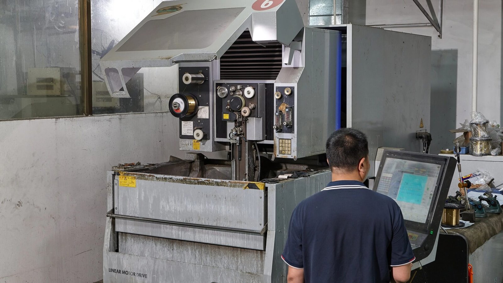
At ZHIXIANG, our precision manufacturing team uses:
- Slow-wire EDM for profile cutting with ±0.001mm accuracy
- Jig grinding for final sizing of critical holes and profiles
- Surface grinding to maintain flatness and parallelism within 0.002mm
- CMM inspection to verify every component against design dimensions
These processes are carried out in a climate-controlled environment to minimize thermal effects on measurement accuracy.
Assembly and alignment discipline
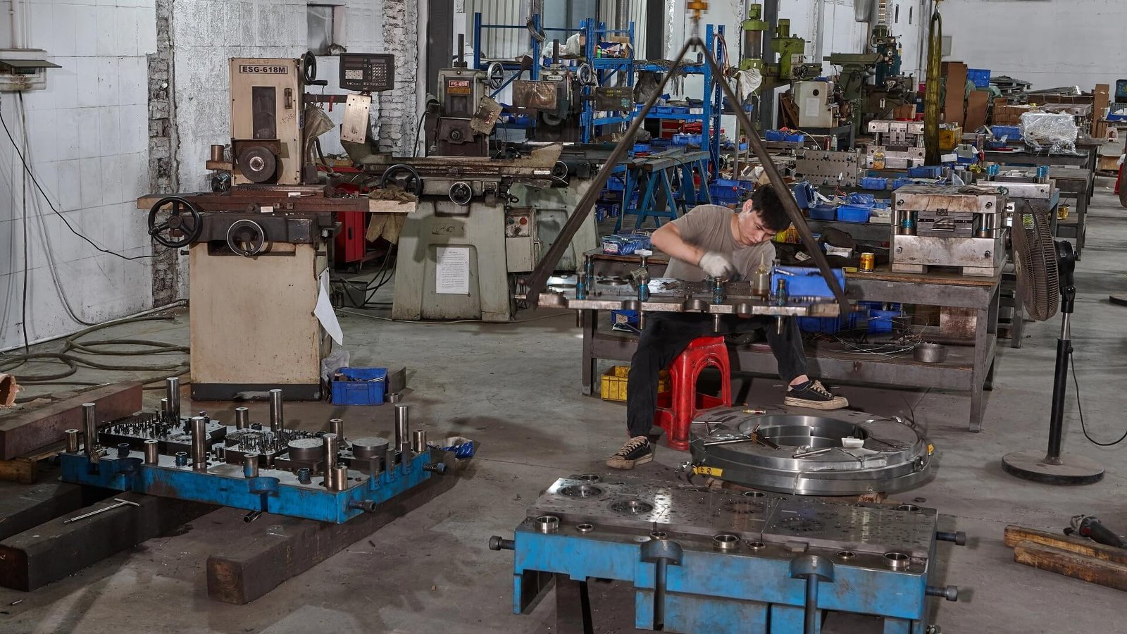
Die assembly is performed with the same precision as component manufacturing. Our assembly process includes:
- Bench assembly under controlled conditions to prevent contamination and misalignment
- Post-assembly CMM verification of punch-to-die clearance at every station
- Laser alignment to ensure all stations are positioned relative to a common reference
This level of assembly discipline ensures that the tight clearances designed for servo/stepper motor dies are actually realized in the finished tool.
Verification and documentation
Every die we build undergoes comprehensive tryout on the customer’s specified silicon steel, with detailed inspection of burr height, dimensional accuracy, and concentricity. Our quality control team documents all measurements and provides complete tryout reports with every die, giving customers confidence in the tool’s performance before it reaches their production floor.
7. Auto-Stacking and Gluing for Servo/Stepper Cores
The choice between auto-interlocking and gluing for servo/stepper motor cores follows similar logic to other motor types, with some nuances.
Auto-interlocking
Auto-interlocking is the dominant stacking method for stepper motors and many servo applications. The interlocking dimples provide immediate stack integrity without additional processing, making it suitable for high-volume production. The die must form the dimples with precise depth and geometry to ensure reliable stacking without damaging the insulation coating.
For stepper motors with high pole counts, the interlocking pattern must be carefully designed to maintain rotational alignment of the stack. This is particularly important because stepper motor performance depends on precise pole alignment.
Gluing (self-adhesive bonding)
Some premium servo applications specify gluing to maximize magnetic performance. Bonded cores offer full electrical isolation between laminations, reducing interlaminar eddy currents and improving efficiency. The die must produce flat, adhesive-ready surfaces without interlock dimples.
The gluing versus interlocking decision is covered in depth in our article on EV motor core die design. While that article focuses on EV traction motors, the technical trade-offs apply equally to high-performance servo motors.
8. Balancing Speed and Precision in Servo/Stepper Motor Stamping
Servo and stepper motor production often operates at high speeds to meet volume demands, but the precision requirements remain stringent. Balancing speed and precision is a central challenge in die design.
Thermal management
At high speeds, frictional heat causes thermal expansion of die components, which can alter clearances and affect part dimensions. For servo/stepper dies, thermal management is particularly critical because the tolerances are so tight. Strategies include:
- Carbide cutting edges with high thermal conductivity to dissipate heat
- MQL lubrication to provide evaporative cooling at the cutting interface
- Directed air cooling for continuous convective cooling
- Thermal compensation in clearance calculations to account for operating temperature expansion
Vibration control
High-speed operation can excite natural frequencies in the die structure, causing vibration that degrades precision. Mitigation measures include:
- Rigid die set construction to raise natural frequencies above the operating range
- Ball-bearing guidance to eliminate play
- Vibration-damping materials in strategic locations
These strategies are covered comprehensively in our article on high-speed stamping die design optimization, and they are implemented as standard in our servo/stepper motor dies.
9. Case Example: Servo Motor Core Die for Industrial Automation
To illustrate how these principles translate into practice, consider a recent servo motor core die project for an industrial automation application:
Motor specifications:
- Stator OD: 80mm
- Rotor OD: 50mm
- Stator slots: 24
- Rotor poles: 8
- Silicon steel: 0.27mm M270-35A (2.2% Si)
- Insulation coating: C5 semi-organic
- Stacking: Auto-interlocking, 8 dimples per stator lamination
- Air gap concentricity requirement: ≤0.020mm
- Burr requirement: ≤0.010mm
- Target speed: 450 SPM
Die specifications:
| Parameter | Specification | Rationale |
|---|---|---|
| Die type | Progressive die, 16 stations | High precision and speed for volume production |
| Cutting components | Sub-micron tungsten carbide (WC-6Co) | Wear resistance and minimal deflection |
| Punch coating | DLC on all cutting punches | Low friction, anti-adhesion on C5 coating |
| Die insert coating | TiAlN | Thermal stability and abrasive resistance |
| Guidance | Ball-bearing guides + fully guided stripper | Zero-play at 450 SPM |
| Clearance (cold) | 0.015mm per side (5.5% t, thermally compensated) | Optimal running clearance at temperature |
| Lubrication | MQL vanishing oil, 7 ml/hour | Minimal residue, effective cooling |
Performance results:
| Metric | Result |
|---|---|
| First tryout burr height | 0.004–0.007mm |
| Burr height at 50M strokes | 0.006–0.009mm |
| Air gap concentricity | 0.015mm (requirement ≤0.020mm) |
| Slot width variation | ±0.003mm |
| Stack height variation | ±0.04mm |
| First regrind | At 80 million strokes |
| Total projected die life | >250 million strokes |
This project — typical of our work with Servo & Stepper Motor customers — demonstrates that ultra-precision and high-speed production are not mutually exclusive. With proper design, material selection, and manufacturing discipline, servo motor core dies can deliver the precision demanded by motion control applications while maintaining the productivity required for industrial automation.
10. Conclusion: Precision Is a System, Not a Setting
Achieving ultra-precision in servo and stepper motor core stamping is not a matter of selecting a single “precision” feature. It is a system-level achievement that encompasses:
- Design that accounts for slender punches, high slot counts, and thermal dynamics
- Materials that provide stiffness, wear resistance, and dimensional stability
- Manufacturing that delivers sub-micron accuracy in every component
- Assembly that realizes the design intent with exacting alignment
- Process control that maintains precision throughout the die’s life
At ZHIXIANG (motordie.com), we have spent over two decades perfecting this system for the most demanding precision motor applications. Our servo and stepper motor core dies deliver the tight tolerances, consistent quality, and long tool life that motion control manufacturers require. From motor core progressive dies with fully guided strippers to tungsten carbide stamping dies with optimized coatings, every tool we build is engineered for precision from the ground up.
Ready to elevate your servo or stepper motor core production? Send us your lamination drawing, silicon steel specification, and precision requirements. Our engineering team will provide a detailed technical proposal — including tool design, material selection, and tolerance analysis — within 48 hours. Send your drawing today and let’s build the precision tooling your motion control products deserve.