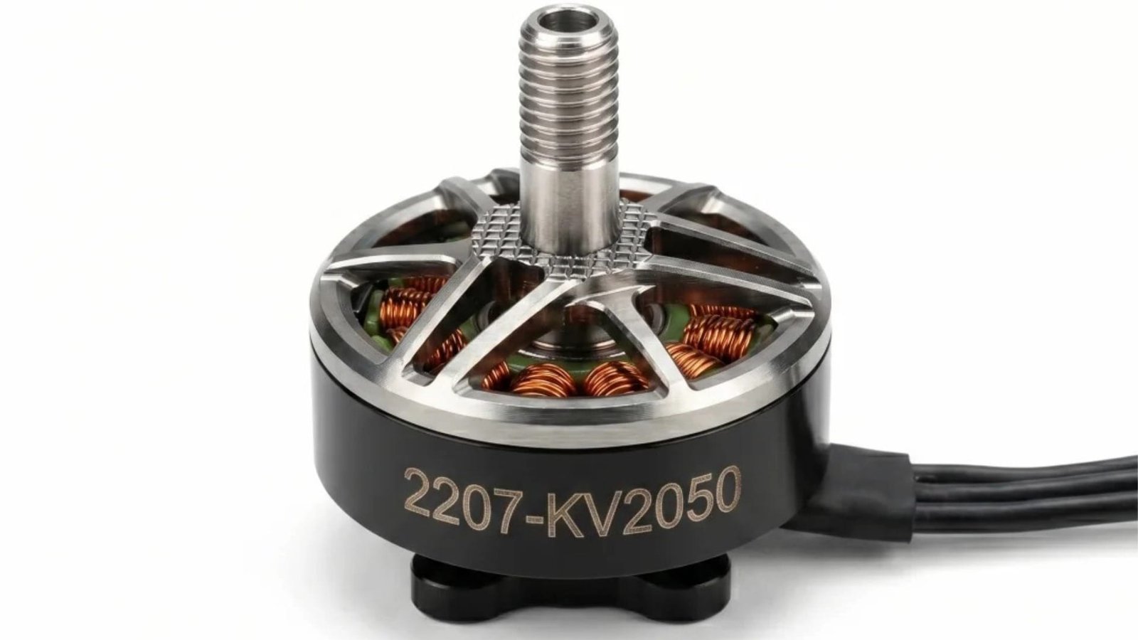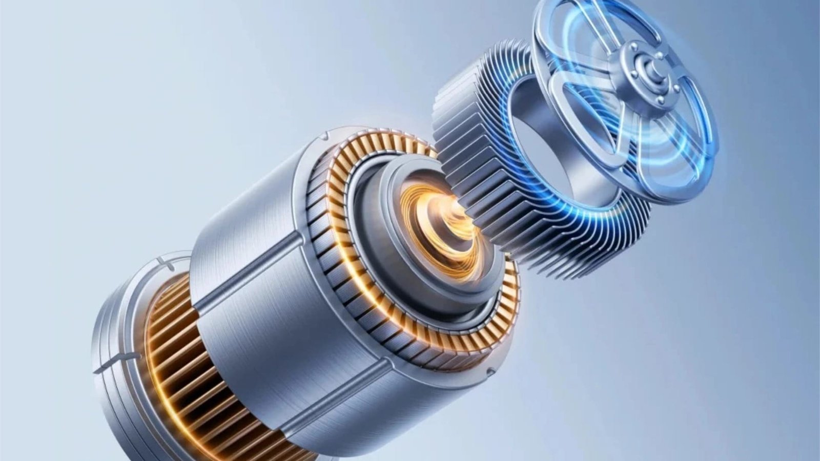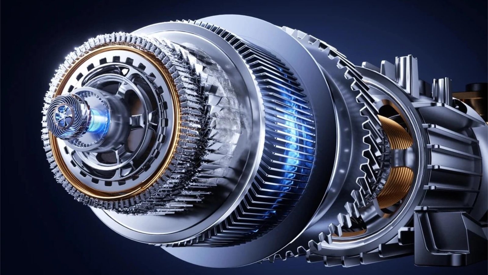
Industrial motors are the workhorses of global infrastructure. They drive the pumps that move water through municipal systems, the fans that ventilate mines and tunnels, the compressors that power refrigeration plants, the conveyors that transport raw materials, and the machine tools that shape metal into precision components. Unlike their more glamorous counterparts in electric vehicles or servo systems, industrial motors are rarely discussed in technology headlines. Yet they account for a substantial share of global electricity consumption — and their efficiency and reliability depend directly on the quality of their laminated cores.
Designing and manufacturing stamping dies for industrial motor laminations presents a unique set of challenges. The large diameters involved — often 200mm to over 1000mm — demand exceptional structural rigidity. The thicker silicon steel grades typically used — 0.50mm and 0.65mm — require different clearance strategies and burr control approaches than the thin-gauge materials used in EV motors. And the production volumes, while often lower than consumer applications, demand long tool life and consistent precision over many years of service.
This article examines the design considerations, technical challenges, and proven solutions for industrial motor core stamping dies. Whether you are sourcing tooling for a new pump motor platform, a large fan motor, or a heavy-duty conveyor drive, this guide will help you understand the factors that separate robust, long-lasting tooling from mediocre alternatives. Visit our Industrial Motor solutions page for additional context on our capabilities in this segment.
1. The Backbone of Industry: Industrial Motors and Their Tooling
Industrial motors are defined less by their technology and more by their application environment. They are expected to operate reliably for decades, often in harsh conditions — high ambient temperatures, dust, moisture, and continuous duty cycles. A typical industrial motor in a water treatment plant may run 24 hours a day, 7 days a week, for 15–20 years before replacement.
The performance demands on these motors are substantial:
- High efficiency: Energy regulations such as IE3 and IE4 efficiency classes have pushed industrial motor manufacturers to continuously improve core quality. A more precise lamination with better stacking factor and tighter air gap reduces iron losses, directly improving motor efficiency.
- Reliability and durability: Industrial motors must maintain their performance over millions of operating hours. The laminated core must remain dimensionally stable and magnetically consistent throughout the motor’s service life.
- Cost-effectiveness: The industrial motor market is highly competitive, with pressure on manufacturers to control costs while meeting increasingly stringent efficiency standards. Tooling must balance performance with economic considerations.
- Wide size range: Industrial motors span a vast range — from 1 kW to over 1 MW. Tooling must accommodate stator diameters from under 100mm to well over 1000mm, each with its own design challenges.
The lamination die is the foundation of every industrial motor. It determines the precision of the air gap, the consistency of the slot geometry, and the quality of the stacking — all of which directly affect motor efficiency, noise, and reliability. A well-designed die produces laminations that assemble into a core with uniform magnetic properties and minimal losses. A poorly designed die produces cores that waste energy, generate noise, and fail prematurely.
At ZHIXIANG, we have been building industrial motor core dies for decades, and our die design and engineering team understands the full spectrum of challenges — from small-frame motors for HVAC blowers to massive stators for mining conveyor drives. This article shares that experience in a structured, practical format.
2. Key Characteristics of Industrial Motor Cores
Industrial motor cores differ significantly from those of other motor types. Understanding these differences is essential for effective die design.
Size range and geometry
Industrial motor stators span an enormous range:
| Motor Type | Typical Stator OD | Stack Height Range | Common Slot Counts |
|---|---|---|---|
| Small industrial | 100–160mm | 80–150mm | 24–36 slots |
| Medium industrial | 160–315mm | 120–250mm | 36–48 slots |
| Large industrial | 315–500mm | 200–400mm | 48–72 slots |
| Extra-large (mill drives, generators) | 500–1000mm+ | 300–800mm+ | 72–144 slots |
The large diameters involved mean that industrial motor dies are substantially bigger than dies for smaller motor types. A die for a 500mm stator may have a die plate spanning 1200mm or more, weighing several tons. This size creates significant challenges in die set rigidity, parallelism, and thermal management.
Silicon steel grades and thicknesses
Industrial motors predominantly use thicker silicon steel grades:
| Efficiency Class | Typical Thickness | Common Grades |
|---|---|---|
| Standard (IE1/IE2) | 0.50–0.65mm | 50A470, 50W600, 65A800 |
| High efficiency (IE3) | 0.50mm | 50A350, 50W470 |
| Premium (IE4+) | 0.35–0.50mm | 35A300, 50A350 |
The thicker materials used in industrial motors are more forgiving in terms of burr control than the thin-gauge EV materials, but they introduce their own challenges: higher cutting forces, more demanding punch strength requirements, and different clearance optimization needs. Our article on silicon steel grade and insulation coating impact provides a detailed treatment of these material considerations.
Slot geometry and special features
Industrial motor stators often feature:
- Deep, wide slots to accommodate large winding cross-sections. While these slots are not as narrow as those in BLDC motors, they are deep — requiring long punches with robust guidance.
- Open or semi-open slot openings for ease of winding insertion. Open slots simplify winding but may require specialized punch geometry.
- Ventilation ducts in the stack for cooling. These are created either by stamping special duct laminations or by inserting spacers during stacking.
- Key slots or alignment features for stack assembly. These ensure that laminations are assembled with correct rotational alignment.
- Large air gaps compared to servo motors (typically 0.35–0.80mm), but consistency remains critical for noise and efficiency.
Stacking methods
Industrial motor cores use several stacking methods:
- Welded stacks: Very common for medium and large industrial motors. The stack is welded along the outside diameter after assembly, providing strong mechanical integrity. The die must produce laminations with good edge quality and no burr interference for welding.
- Bolted or riveted stacks: Used for very large motors where welding is impractical. The die must include holes for the bolts or rivets.
- Auto-interlocking: Increasingly used for small and medium industrial motors, particularly for high-volume production. The die forms dimples that mechanically join laminations.
- Gluing (self-adhesive bonding): Growing in popularity for premium-efficiency industrial motors, particularly where minimizing interlaminar eddy currents is critical.
The choice of stacking method affects die design significantly, as each requires different tooling features. The interlocking versus gluing trade-off is discussed in detail in our article on EV motor core die design, and the same principles apply to industrial motor cores.
3. Unique Design Challenges in Large Industrial Motor Core Dies
Structural rigidity and parallelism
The single greatest challenge in large industrial motor die design is maintaining structural rigidity. A die plate for a 500mm stator may span 1200mm or more. Under stamping forces of hundreds of tons, even a small amount of flexure produces uneven clearances across the die face, leading to inconsistent burr height and dimensional variation.
The solution requires several coordinated measures:
- Thick, stress-relieved die plates to minimize flexure. For large dies, die plate thicknesses of 60–100mm or more are common.
- Multiple guide posts — typically 4, 6, or even 8 — positioned to distribute alignment forces evenly across the die face.
- Precision-ground surfaces to maintain parallelism within 0.005–0.010mm across the entire die area.
- Rigid upper and lower die shoes with minimal overhang and adequate thickness.
- Strategic ribbing or reinforcement in areas of high stress concentration.
These measures ensure that the large die structure behaves as a solid, stable platform. Our precision manufacturing team applies these principles to every large-format die we build, using precision grinding and laser alignment to verify flatness and parallelism.
Thick-material cutting forces and clearance optimization
Industrial motor laminations use thicker silicon steel than EV or servo motors — typically 0.50mm or 0.65mm. This thicker material generates significantly higher cutting forces and requires different clearance optimization.
For 0.50mm silicon steel, the recommended clearance is typically 5–6% of material thickness per side — 0.025–0.030mm. For 0.65mm material, the clearance increases to 0.033–0.039mm per side. These larger clearances are easier to achieve and maintain than the micron-level clearances required for thin-gauge EV materials, but they must still be held uniformly across the die face.
The higher cutting forces also demand more robust punch construction. Punches for thick material need larger cross-sections, shorter unsupported lengths, and stronger retention systems. Backing plates must be adequately specified to distribute the load without deformation.
Our article on reducing burr height in motor lamination stamping covers clearance optimization in detail, including the specific considerations for thicker materials.
Long punch guidance and support
Although industrial motor slots are typically wider than those in BLDC motors, they can be quite deep — often 50–80mm in large motors. The punches that cut these slots have high length-to-width ratios, making them susceptible to buckling and deflection.
Managing these long punches requires:
- Stepped punch designs with larger bodies and only the working tip at final size.
- Multi-level guided strippers that provide support at multiple points along the punch length.
- Carbide or high-strength PM steel punch material to maximize stiffness.
- Careful punch length optimization to minimize unsupported length.
The principles are similar to those discussed in our BLDC motor core die design article, but the scale is larger and the forces are higher, demanding even more attention to structural support.
Die weight, handling, and installation
Large industrial motor dies are heavy — often 2–10 tons or more. This weight creates practical challenges:
- Die handling: Moving a 5-ton die requires specialized lifting equipment and careful rigging. The die must be designed with lifting points, and the press area must have adequate crane capacity.
- Die installation: Aligning a large die in the press requires precision procedures and often laser alignment tools. Misalignment during installation can cause immediate damage.
- Die storage: Large dies take up significant floor space and must be stored on rigid supports to prevent distortion.
- Thermal mass: The large mass of the die affects its thermal behavior. It heats up slowly but also cools slowly, and thermal gradients across the die can cause distortion.
These practical considerations are often overlooked in the design phase but have a major impact on production efficiency and die longevity. A well-designed large die includes handling features and installation aids that make these tasks safer and more precise.
Thermal management and stamping speed
Large industrial motor dies rarely run at the high speeds used for EV or BLDC production. Typical speeds are 60–150 SPM for very large dies, and 150–250 SPM for medium industrial motors. The reasons are primarily structural: larger dies have higher moving masses and lower natural frequencies, limiting safe operating speeds.
However, thermal management remains important. The high cutting forces generate significant heat, and the large die mass means that temperature gradients can develop across the die face, causing distortion. This is particularly true when the stamping operation runs continuously for hours.
Strategies for thermal management in large dies include:
- Directed air cooling at the cutting zones.
- Lubricant cooling through the MQL system.
- Thermal isolation of critical alignment features from heat sources.
- Speed optimization to balance productivity with thermal loading.
Our article on high-speed stamping die design optimization provides additional context, though the specific speed ranges for large industrial dies are lower than those discussed there.
4. Progressive vs. Compound Die Selection for Industrial Motors
The choice between a motor core progressive die and a motor core compound die is a fundamental decision for industrial motor tooling. This decision should be based on production volume, lamination size, and complexity. Our comprehensive guide on choosing the right motor core stamping die provides the general decision framework; here we focus on industrial motor-specific considerations.
Progressive die advantages for industrial motors
- Higher production speed: Progressive dies run at 100–250 SPM for medium industrial stators, far exceeding compound die speeds.
- Integration of auto-stacking: For manufacturers adopting interlocking stacks, progressive dies provide in-die stacking capability.
- Complex feature capability: Progressive dies can produce ventilation holes, key slots, and other features in a single pass.
- Material efficiency: Optimized strip layouts minimize scrap, important for cost-sensitive industrial production.
Compound die advantages for industrial motors
- Lower initial cost: Compound dies are significantly less expensive to build, making them attractive for the medium production volumes typical of industrial motors.
- Excellent concentricity: Cutting the complete stator and rotor in a single stroke ensures perfect alignment — critical for motor efficiency and noise control.
- Large diameter capability: Compound dies handle very large laminations more economically than progressive dies.
- Simpler maintenance: Single-station design means fewer components to maintain and troubleshoot.
Decision factors for industrial motors
| Factor | Progressive Die | Compound Die |
|---|---|---|
| Production volume > 500,000/year | ✓ Recommended | — |
| Production volume < 200,000/year | — | ✓ Recommended |
| Stator OD > 400mm | Possible (large die) | ✓ Recommended |
| Auto-stacking required | ✓ Recommended | Not available |
| Welded or bolted stacking | Possible | ✓ Recommended |
| Complex geometry with many features | ✓ Recommended | Limited |
| Budget-constrained project | Higher initial cost | Lower initial cost |
For many industrial motor applications — particularly larger frame sizes produced in moderate volumes — the motor core compound die remains the preferred choice. Its inherent concentricity advantage and lower cost make it ideal for applications where production volumes do not justify a progressive tool. For high-volume smaller industrial motors, the progressive die offers the speed and integration benefits that justify the higher initial investment.
Many industrial motor manufacturers use a combination of both: compound dies for large frames and progressive dies for smaller high-volume frames. The optimal choice depends on your specific product mix and production requirements.
5. Tool Material and Coating Selection for Large Dies
The material and coating choices for industrial motor dies must balance performance with cost, particularly given the large size of the components involved.
Tool materials for industrial motor dies
For large industrial motor dies, the material strategy differs from smaller precision dies:
- D2 / DC53 tool steel: For medium and large compound dies and progressive die structural components, conventional tool steels remain cost-effective. Their larger carbide size is less problematic in thick material stamping, and their lower cost is advantageous for large components.
- Powder metallurgy steel (ASP23, VANADIS 4): For progressive die cutting punches and high-wear die inserts, PM steels offer better wear resistance and toughness than conventional grades. They are a good middle option between tool steel and carbide.
- Tungsten carbide: For high-volume progressive dies and critical wear components, carbide delivers the longest life. However, the cost of large carbide components is significant, so carbide is often used selectively — for cutting edges and high-wear inserts rather than entire die plates.
Our article on motor core die materials provides a detailed comparison of these materials and their performance characteristics.
Coatings for industrial motor dies
The silicon steel used in industrial motors — typically with C4 or C5 insulation coatings — benefits from PVD coating selection:
- TiCN (Titanium Carbonitride): Excellent for abrasive coatings at typical industrial stamping speeds (100–200 SPM).
- TiAlN (Titanium Aluminum Nitride): Superior for higher-speed operation where thermal stability is critical.
- CrN (Chromium Nitride): Effective for semi-organic coatings where anti-galling is beneficial.
The coating decision should be integrated with the material selection to achieve the optimal balance of performance and cost. Our article on advanced surface treatments for motor core dies provides comprehensive guidance on coating selection for different applications.
Hybrid material strategies
For large industrial dies, a hybrid approach is often the most economical:
- Tungsten carbide inserts at the highest-wear cutting stations.
- PM tool steel for medium-wear punches and die inserts.
- Conventional tool steel for structural components — die plates, strippers, guides.
This targeted approach delivers the performance benefits where they matter most while controlling costs on the large structural components. At ZHIXIANG, we routinely specify hybrid material configurations for industrial motor dies, optimizing both performance and investment.
6. Achieving Precision and Consistency in Large-Diameter Stamping
The ultimate measure of an industrial motor core die is not its performance at tryout but its consistency over years of production. Achieving and maintaining precision in large-diameter stamping requires attention to several factors.
Air gap concentricity in large dies
The air gap in an industrial motor is typically larger than in a servo motor — often 0.35–0.80mm — but consistency remains critical. A concentricity error of 0.05mm in a motor with a nominal 0.50mm air gap represents a 10% magnetic flux variation, which produces uneven torque, increased noise, and reduced efficiency.
For compound dies, concentricity is inherent — the stator ID and rotor OD are cut in a single stroke. For progressive dies, maintaining concentricity requires meticulous station-to-station alignment and piloting accuracy. Our precision manufacturing team uses slow-wire EDM, jig grinding, and CMM verification to ensure that every component meets exacting tolerances.
Burr control in thick material
Burr control in thick material (0.50–0.65mm) is different from thin-gauge applications. The allowable burr height is proportionally larger — typically 5% of material thickness, or 0.025–0.033mm for 0.50–0.65mm materials. However, the larger cutting forces and thicker material make achieving and maintaining these burr heights more challenging.
Key factors include:
- Optimal clearance in the 5–6% range, maintained uniformly across the die.
- Sharp cutting edges maintained through regular regrinding and premium edge materials.
- Rigid punch guidance to prevent deflection-induced clearance variation.
- Proper material support to prevent the thick strip from moving during cutting.
Our article on reducing burr height in motor lamination stamping provides detailed measurement and control strategies.
Structural rigidity and alignment verification
For large dies, structural rigidity is the foundation of precision. After assembly, the die should be verified for:
- Plate parallelism across the entire die face.
- Guide post alignment and play at all locations.
- Punch-to-die clearance at every station.
- Die shoe flatness on the bolster plate.
These verifications require precision measurement equipment — laser alignment systems, CMM, and precision levels. Our quality control team performs these verifications on every large die we build, documenting the results and providing complete reports to the customer.
Thermal stability in continuous production
Large industrial dies may run continuously for hours or days. The heat generated during stamping causes thermal expansion, which can affect clearances and dimensions. Managing this thermal effect requires:
- Thermal compensation in the clearance calculations, accounting for the expected operating temperature.
- Cooling strategies to minimize temperature rise and thermal gradients.
- Regular dimensional monitoring during long production runs to detect drift early.
The thermal challenges in large dies are addressed in our article on high-speed stamping die design optimization, which covers thermal management strategies applicable to all die sizes.
7. Maintenance and Refurbishment of Large Industrial Motor Dies
Large industrial motor dies have unique maintenance considerations due to their size, weight, and long service life.
Maintenance access and ergonomics
Working on a large die — whether for inspection, cleaning, or component replacement — requires careful planning:
- Lifting and handling: The die must be lifted and positioned safely. Maintenance areas need adequate crane capacity and clear floor space.
- Access to internal stations: For progressive dies, internal stations may be difficult to reach. The die should be designed with removable sections or access panels where possible.
- Inspection access: Critical wear points should be visible and measurable without full disassembly. Inspection ports and easily removable inserts facilitate this.
Our article on preventive maintenance provides a complete framework for establishing a maintenance program, and the principles apply directly to large industrial dies.
Regrinding and component replacement
Regrinding of large die components requires specialized equipment:
- Large surface grinders with sufficient table size to accommodate the components.
- Precision handling equipment to move heavy components during the regrinding process.
- Skilled operators experienced in working with large, expensive components.
For compound dies, regrinding typically involves the punch plate and die plate simultaneously to maintain clearance. For progressive dies, individual punches and inserts are reground to their specified dimensions.
Refurbishment decision-making for large dies
Large industrial motor dies represent significant capital investments. The decision to refurbish or replace should be made carefully, considering:
- Remaining useful life of the die structure and components.
- Cost of refurbishment compared to new die cost.
- Product design stability — will the motor design remain current for the projected extended life?
- Technology advances — would a new die offer significant performance improvements?
Our article on motor core die refurbishment provides a complete decision framework for these situations.
Spare parts management for large dies
Large dies have unique spare parts considerations:
- Component cost: Large punches and die inserts are expensive, so inventory levels must be balanced against capital costs.
- Lead time: Custom components for large dies often have longer lead times than standard parts. Ordering must account for this.
- Criticality: Components that would cause extended downtime if they fail should be prioritized for inventory.
Our spare parts and tooling components service supports industrial motor die customers with component sourcing and stocking recommendations.
8. Case Example: Industrial Motor Core Die for a Pump Motor
To illustrate these principles in practice, consider a recent industrial motor core die project for a water pump application:
Motor specifications:
- Stator OD: 280mm
- Rotor OD: 170mm
- Stator slots: 48
- Rotor slots: 40
- Silicon steel: 0.50mm 50A470 (1.8% Si)
- Insulation coating: C5 semi-organic
- Stacking: Welded stack (no interlocking)
- Air gap requirement: 0.50mm ±0.035mm
- Burr requirement: ≤0.025mm
- Production volume: 80,000 motors/year
- Target speed: 80 SPM (compound die)
Die specifications:
| Parameter | Specification | Rationale |
|---|---|---|
| Die type | Compound die | Medium volume, large diameter, welded stacking |
| Die set size | 800mm × 700mm | Large diameter stator |
| Cutting components | D2 tool steel (60–62 HRC) with TiCN coating | Cost-effective for medium volume, thick material |
| Die plate thickness | 80mm (upper and lower) | Structural rigidity |
| Guidance system | 6 ball-bearing guide posts | Zero-play on large die structure |
| Clearance | 0.028mm per side (5.6% t) | Optimal for 0.50mm material |
| Lubrication | MQL vanishing oil, 12 ml/hour | Large die area requires adequate coverage |
| Die weight | 3.8 tons | Requires crane for installation |
Performance results:
| Metric | Result |
|---|---|
| First tryout burr height | 0.010–0.015mm |
| Burr height at 10M strokes | 0.012–0.018mm |
| Air gap concentricity | 0.028mm (requirement ≤0.035mm) |
| Slot width variation | ±0.008mm |
| Stack height consistency | ±0.10mm |
| First regrind | At 15 million strokes |
| Total projected die life | >50 million strokes (with periodic regrinds) |
This project — representative of our work with Industrial Motor customers — demonstrates that large compound dies can achieve excellent precision and consistency at medium production volumes, with cost-effective tooling materials and robust construction.
9. Conclusion: Partnering for Large-Scale Motor Core Tooling Success
Industrial motor core dies may not command the same technological attention as EV traction motor tooling, but they represent a demanding engineering challenge in their own right. The combination of large dimensions, thick materials, high cutting forces, and long service life requirements creates a tooling environment where structural rigidity, material selection, and manufacturing precision are equally critical.
At ZHIXIANG (motordie.com), we have been building industrial motor core dies for decades. Our die design and engineering team understands the unique requirements of large-diameter tooling, our precision manufacturing capabilities ensure that every component meets exacting tolerances regardless of size, and our quality control process verifies performance before delivery.
Whether you are producing pump motors at 80 SPM on a compound die, or high-volume small industrial motors on a progressive die, we have the experience and capability to deliver the robust, precision tooling you need.
Ready to optimize your industrial motor core tooling? Send us your lamination drawing, silicon steel specification, and production requirements. Our engineering team will provide a detailed technical proposal — including die type recommendation, material selection, and tolerance analysis — within 48 hours. Send your drawing today.